Qualcomm DSP Kernel Internals
In depth internals on Qualcomm DSP Kernel (FastRPC implementation)
When working with DSP systems and Qualcomm’s FastRPC framework, understanding the internals of the kernel-side implementation can be key to effectively navigating the codebase to understand it and to study complex bugs. In this post, we’ll take a brief look under the hood of the DSP kernel FastRPC implementation. The goal is not to cover every detail, but to build foundational context that can guide further exploration. Let’s dive in.
The codebase referenced in this blog is the
dsp-kernel.lnx.3.2.r4-relbranch of the dsp-kernel repository. I’ve also forked this branch to my GitHub for easier reference. All code snippets and references in this post are based on that version.
Architecture
The FastRPC DSP kernel system is a comprehensive Remote Procedure Call framework that enables high-performance communication between Linux kernel/userspace applications and Digital Signal Processor subsystems on Qualcomm platforms . The system implements a sophisticated multi-layered architecture with three primary components: userspace applications, kernel driver infrastructure, and transport mechanisms .
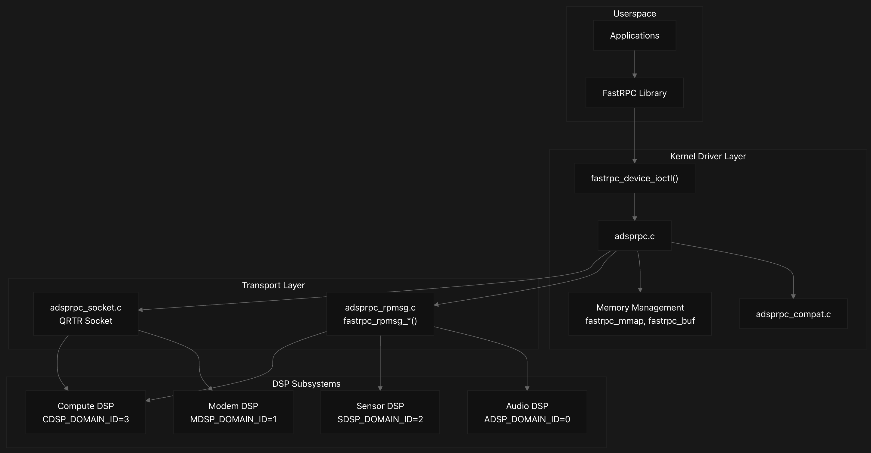
The system supports communication with four primary DSP subsystems, each identified by specific domain IDs:
- ADSP (Audio, ID: 0)
- MDSP (Modem, ID: 1)
- SDSP (Sensors, ID: 2)
- CDSP (Compute, ID: 3)
Each domain is configured with specific subsystem names and service location parameters for proper routing and initialization.
1
2
3
4
5
6
7
8
9
10
11
12
13
14
15
16
17
18
19
20
21
22
23
24
25
26
27
28
29
30
31
32
33
34
35
36
37
38
39
40
41
42
43
44
45
46
struct fastrpc_apps {
	struct fastrpc_channel_ctx *channel;
	struct cdev cdev;
	struct class *class;
	struct smq_phy_page range;
	struct hlist_head maps;
	uint32_t staticpd_flags;
	dev_t dev_no;
	int compat;
	struct hlist_head drivers;
	spinlock_t hlock;
	struct device *dev;
	/* Indicates fastrpc device node info */
	struct device *dev_fastrpc;
	unsigned int latency;
	int transport_initialized;
	/* Flag to determine fastrpc bus registration */
	int fastrpc_bus_register;
	bool legacy_remote_heap;
	/* Unique job id for each message */
	uint64_t jobid[NUM_CHANNELS];
	struct gid_list gidlist;
	struct device *secure_dev;
	struct device *non_secure_dev;
	/* Secure subsystems like ADSP/SLPI will use secure client */
	struct wakeup_source *wake_source_secure;
	/* Non-secure subsystem like CDSP will use regular client */
	struct wakeup_source *wake_source;
	uint32_t duplicate_rsp_err_cnt;
	uint32_t max_size_limit;
	struct hlist_head frpc_devices;
	struct hlist_head frpc_drivers;
	struct mutex mut_uid;
	/* Indicates nsp status */
	int fastrpc_nsp_status;
	/* Indicates secure context bank to be shared */
	int share_securecb;
	/* Indicates process type is configured for SMMU context bank */
	bool cb_pd_type;
	/* Number of lowest capacity cores for given platform */
	unsigned int lowest_capacity_core_count;
	/* Flag to check if PM QoS vote needs to be done for only one core */
	bool single_core_latency_vote;
	/* Maximum sessions allowed to be created per process */
	uint32_t max_sess_per_proc;
};
The system uses a hierarchical structure to manage communication between the Linux kernel and DSP subsystems, centered around the global fastrpc_apps structure which serves as the central coordination point for the entire FastRPC system, instantiated as the global variable gfa. This structure contains several key components like hannel contexts, device information, and job IDs that organize the system’s resources.
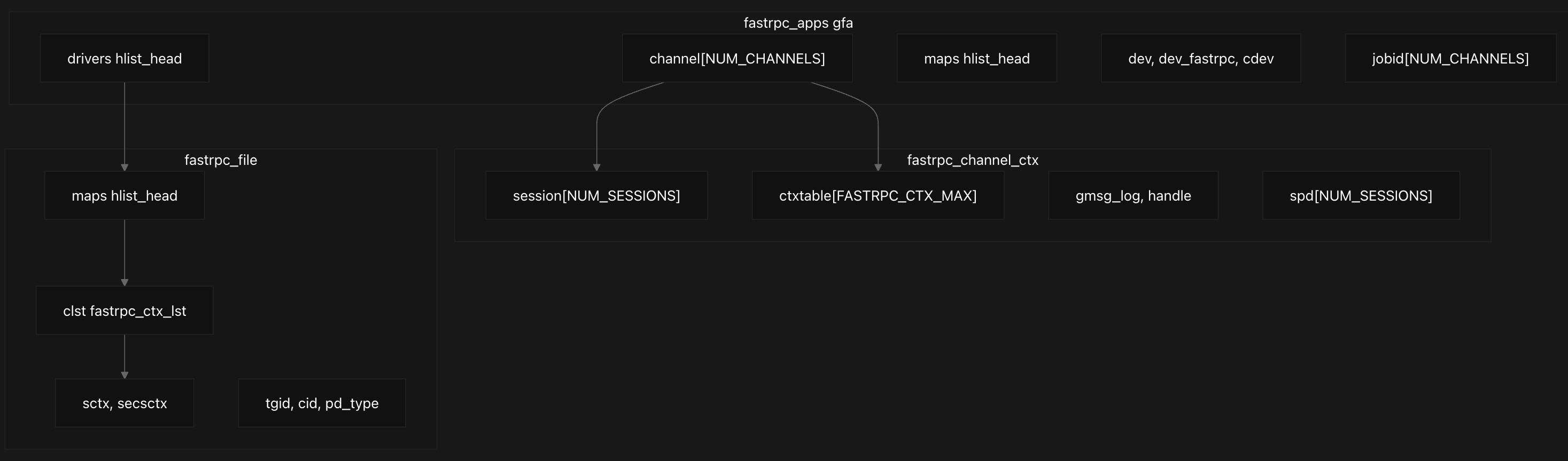
The channel[NUM_CHANNELS] array manages communication channels for different DSP domains (ADSP, MDSP, SDSP, CDSP), while drivers and maps hash lists track registered drivers and memory mappings respectively. Device information is stored in dev, dev_fastrpc, and cdev fields, and each channel maintains its own job ID counter in the jobid[NUM_CHANNELS] array.
Each channel context fastrpc_channel_ctx present in fastrpc_apps contains session management through session[NUM_SESSIONS] and static process domains via spd[NUM_SESSIONS]. The most critical component for RPC tracking is the ctxtable[FASTRPC_CTX_MAX] array, which maintains pointers to active RPC contexts, protected by the ctxlock. Transport logging is handled through gmsg_log and the transport handle.
1
2
3
4
5
6
7
8
9
10
11
12
13
14
15
16
17
18
19
20
21
22
23
24
25
struct fastrpc_file {
	struct hlist_node hn;
	spinlock_t hlock;
	struct hlist_head maps;
	struct hlist_head cached_bufs;
	uint32_t num_cached_buf;
	struct hlist_head remote_bufs;
	struct fastrpc_ctx_lst clst;
	struct fastrpc_session_ctx *sctx;
	struct fastrpc_buf *init_mem;
	struct kref refcount;

	/* No. of persistent headers */
	unsigned int num_pers_hdrs;
	/* Pre-allocated header buffer */
	struct fastrpc_buf *pers_hdr_buf;
	/* Pre-allocated buffer divided into N chunks */
	struct fastrpc_buf *hdr_bufs;
	/* Store snapshot of memory occupied by different buffers */
	struct memory_snapshot mem_snap;

	struct fastrpc_session_ctx *secsctx;

    ...
};
Each userspace process that opens the FastRPC device gets a fastrpc_file structure that tracks process-specific state, memory mappings, and active RPC contexts. At the file level, each fastrpc_file structure represents a client process and contains fields like, its own maps hash list for memory mappings, a context list (clst) of type fastrpc_ctx_lst,channel context fastrpc_channel_ctx, and session contexts (sctx, secsctx) for secure and non-secure operations.
1
2
3
4
5
6
7
8
9
10
struct fastrpc_ctx_lst {
	struct hlist_head pending;
	struct hlist_head interrupted;
	/* Number of active contexts queued to DSP */
	uint32_t num_active_ctxs;
	/* Queue which holds all async job contexts of process */
	struct hlist_head async_queue;
	/* Queue which holds all status notifications of process */
	struct list_head notif_queue;
};
The context list structure fastrpc_ctx_lst organizes RPC contexts into pending, interrupted, and asynchronous queues, enabling efficient management of concurrent operations. Process identification is maintained through tgid, channel ID cid, and process domain type pd_type fields. We’ll be looking at context management in depth now.
Context Management and Lifecycle
The FastRPC context allocation system implements a sophisticated resource management mechanism that combines context table management, ID encoding, and lifecycle tracking to ensure reliable RPC communication between the kernel and DSP subsystems.
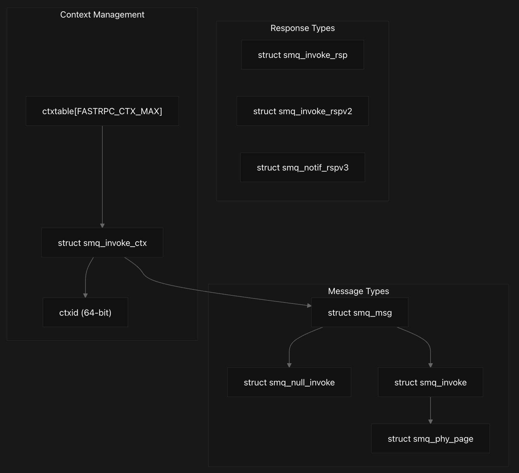
The driver maintains per-channel context tables with ctxtable[FASTRPC_CTX_MAX] as discussed earlier, with 1024 entries, where contexts where each channel has its own ctxtable[FASTRPC_CTX_MAX] array protected by a ctxlock spinlock for thread safety. They are allocated and tracked using a 64-bit context ID that encodes the remote PD type, job type, table index, and incrementing context ID in specific bit ranges.
The context allocation process reserves entries for kernel and static calls while user handles start from a higher index, with the context ID constructed by combining job ID, table index, and job type through bit manipulation. When responses arrive, the system extracts the table index from the context ID to locate the corresponding context entry and validate the response before notifying the waiting thread.
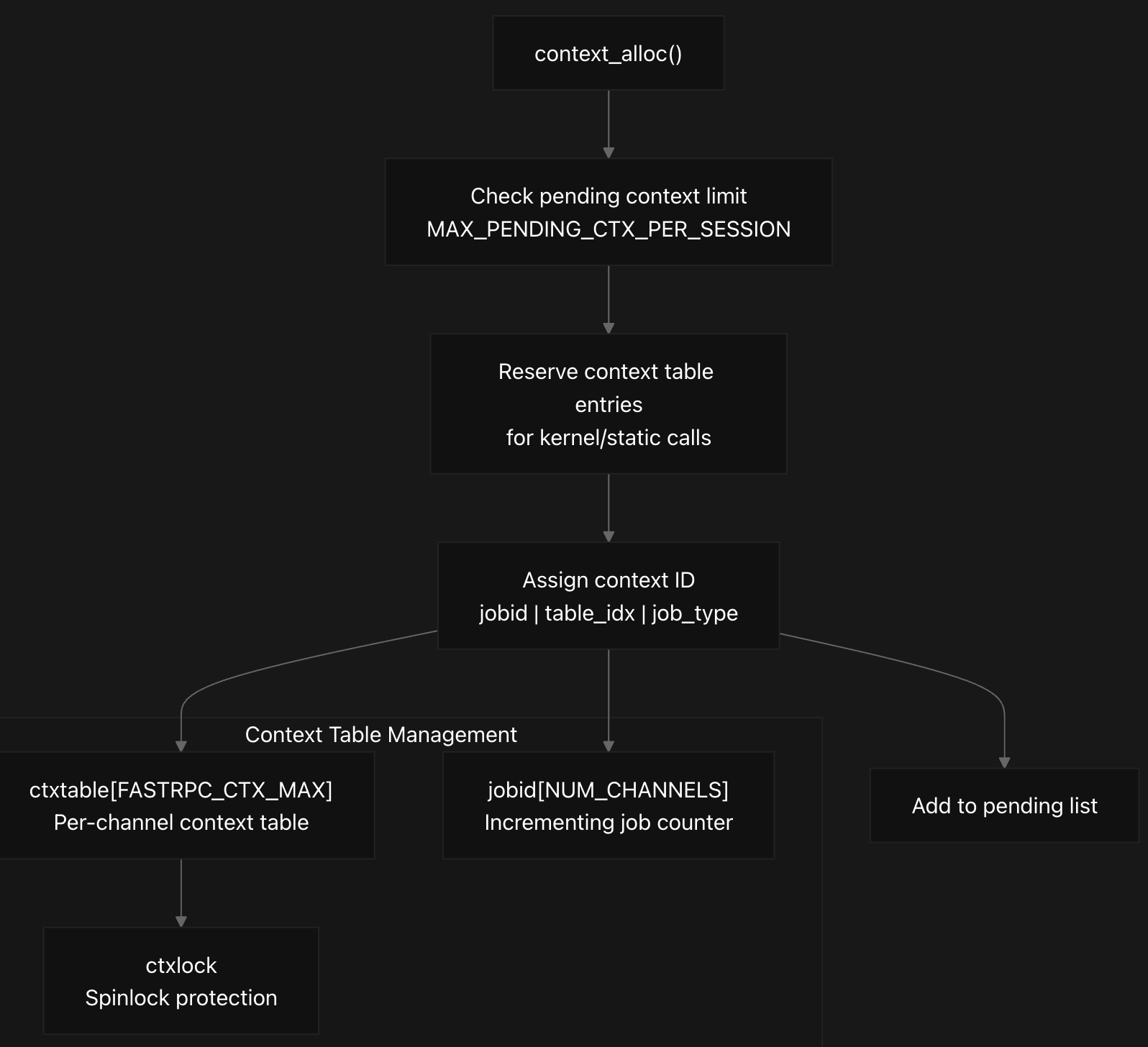
During context allocation in context_alloc, the system first checks if the pending context limit MAX_PENDING_CTX_PER_SESSION(64) has been exceeded to prevent resource exhaustion. The allocation process strategically reserves the first 70 entries (NUM_KERNEL_AND_STATIC_ONLY_CONTEXTS) for critical kernel and static RPC calls, while user contexts start from index 70 to ensure system operations cannot be blocked by user invocations.
The context ID encoding scheme packs multiple components into a single 64-bit identifier using bit manipulation operations. The encoding combines the incrementing job ID (me->jobid[cid]) in bits 16-63, the table index in bits 6-15, the job type (sync/async) in bit 4, and the process domain type in bits 0-3. This design allows efficient extraction of the table index during response processing using the GET_TABLE_IDX_FROM_CTXID macro.
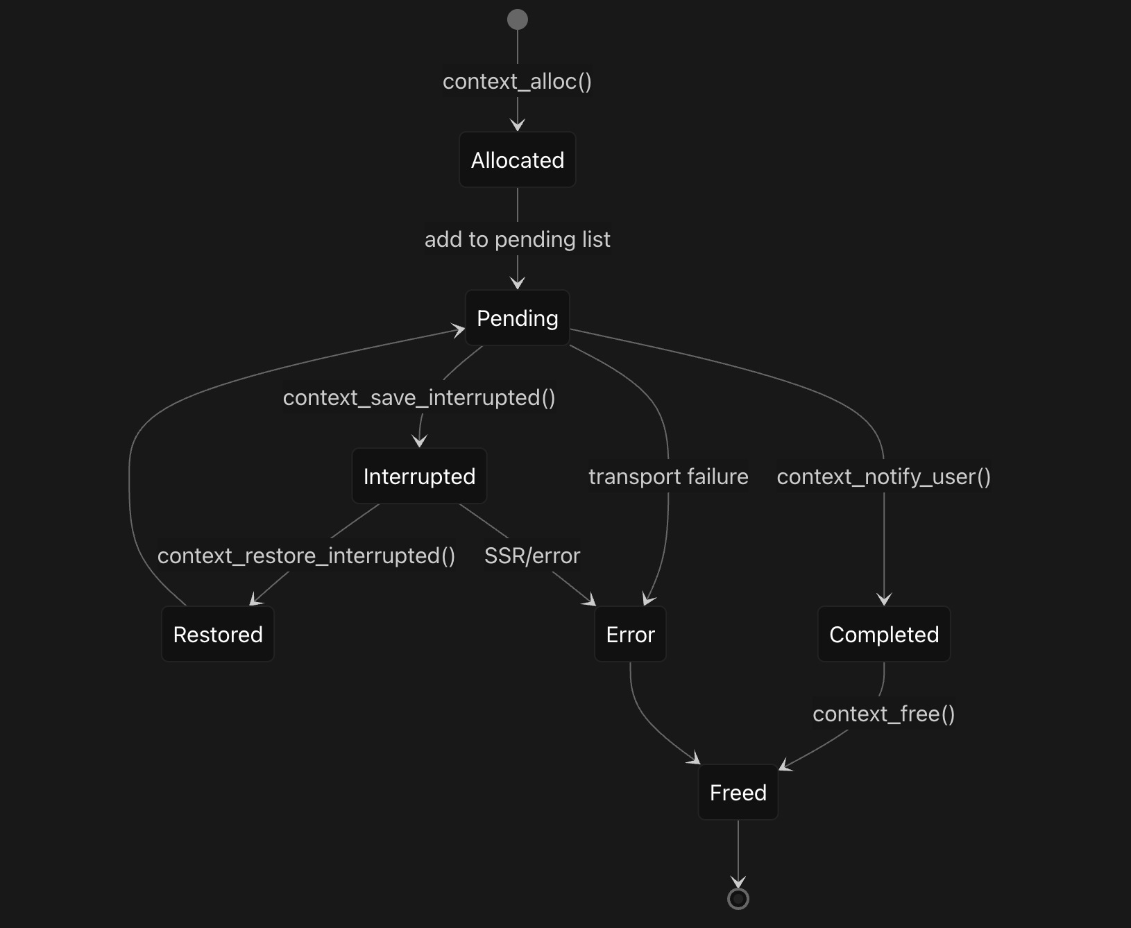
The context lifecycle progresses through multiple states managed by different functions . After allocation, contexts are added to the file’s pending list and the active context count is incremented. The context_save_interrupted function moves contexts to an interrupted state when needed, transferring them from the pending list to the interrupted list. The context_restore_interrupted function reverses this process, moving contexts back to the pending list when they can be resumed.
Context cleanup in context_free systematically reverses the allocation process by first extracting the table index from the context ID and clearing the corresponding entry in the channel’s context table. The function then removes the context from the file’s pending list, decrements the active context count, and frees associated resources including mapped buffers and performance tracking structures. This comprehensive cleanup ensures proper resource management and prevents memory leaks throughout the RPC lifecycle .
RPC Invocation Flow
The RPC invocation flow in the FastRPC DSP kernel system uses the SMQ (Shared Memory Queue) protocol and represents a complete communication pipeline between user applications and Digital Signal Processors. When a user application initiates an RPC call, it triggers a carefully orchestrated sequence that begins with the IOCTL interface and culminates in DSP execution and response handling. It is closely tied with the context management as we’ll see soon.
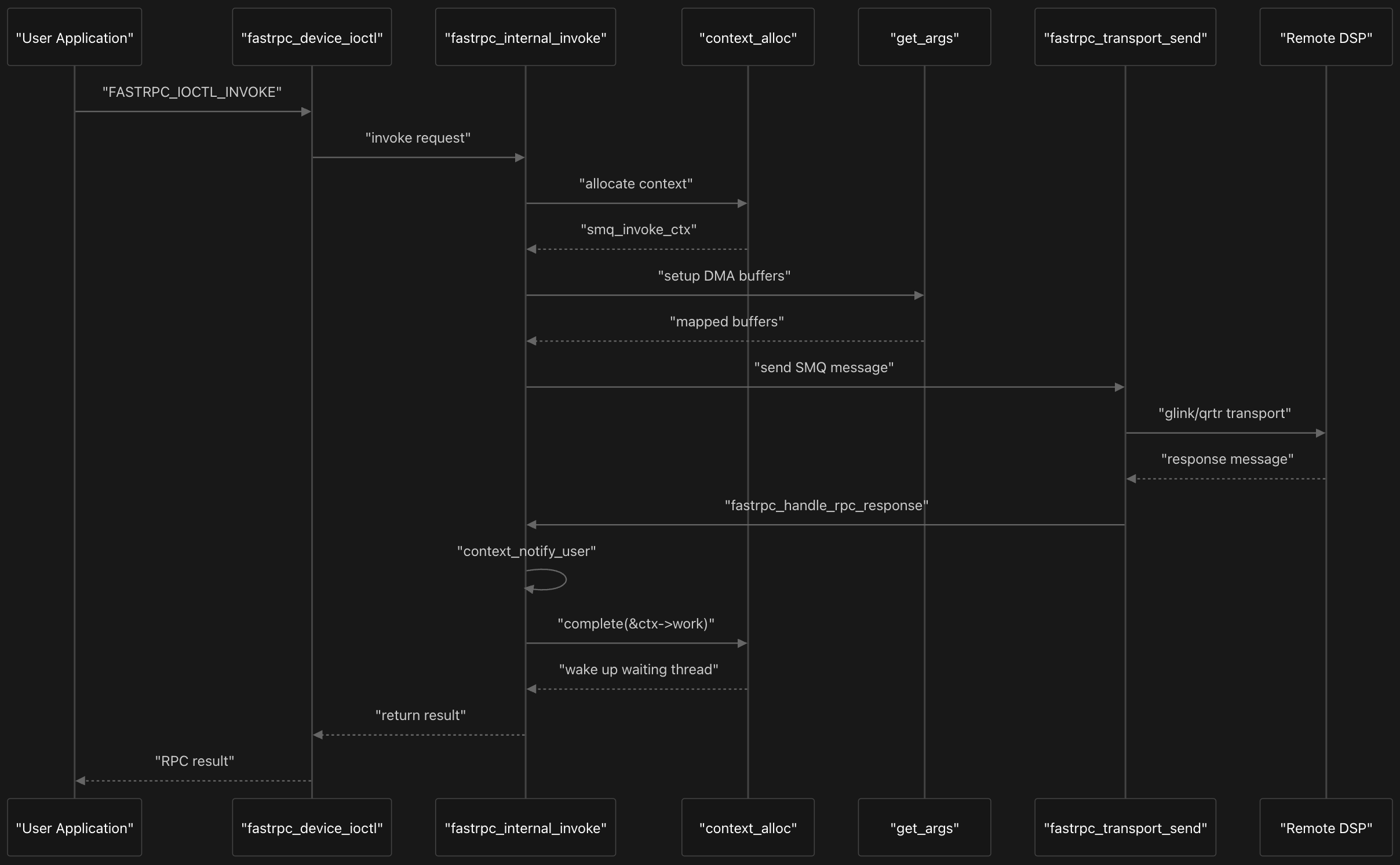
The process starts when user applications make system calls that are intercepted by fastrpc_device_ioctl, which serves as the primary entry point for all FastRPC operations. This function processes various IOCTL commands, with FASTRPC_IOCTL_INVOKE being the most common for standard RPC calls. The IOCTL handler copies user parameters into kernel space and immediately delegates to the core orchestration function.
The central coordinator of the entire flow is fastrpc_internal_invoke, which manages every aspect of the RPC lifecycle from context creation to cleanup. This function first validates the channel ID and session context, then determines whether to restore an interrupted context or allocate a new one. For new invocations, it calls context_alloc to create an smq_invoke_ctx structure that tracks the RPC request throughout its lifetime.
1
2
3
4
5
6
7
8
9
10
11
12
13
14
15
16
17
18
19
20
21
22
23
24
25
26
27
28
29
30
31
32
33
34
35
36
37
38
39
40
41
42
43
44
45
46
47
48
struct smq_invoke_ctx {
	struct hlist_node hn;
	/* Async node to add to async job ctx list */
	struct hlist_node asyncn;
	struct completion work;
	int retval;
	int pid;
	int tgid;
	remote_arg_t *lpra;
	remote_arg64_t *rpra;
	remote_arg64_t *lrpra;		/* Local copy of rpra for put_args */
	int *fds;
	unsigned int *attrs;
	struct fastrpc_mmap **maps;
	struct fastrpc_buf *buf;
	struct fastrpc_buf *copybuf;	/*used to copy non-ion buffers */
	size_t used;
	struct fastrpc_file *fl;
	uint32_t handle;
	uint32_t sc;
	struct overlap *overs;
	struct overlap **overps;
	struct smq_msg msg;
	uint32_t *crc;
	uint64_t *perf_kernel;
	uint64_t *perf_dsp;
	unsigned int magic;
	uint64_t ctxid;
	struct fastrpc_perf *perf;
	/* response flags from remote processor */
	enum fastrpc_response_flags rsp_flags;
	/* user hint of completion time in us */
	uint32_t early_wake_time;
	/* work done status flag */
	bool is_work_done;
	/* Store Async job in the context*/
	struct fastrpc_async_job asyncjob;
	/* Async early flag to check the state of context */
	bool is_early_wakeup;
	uint32_t sc_interrupted;
	struct fastrpc_file *fl_interrupted;
	uint32_t handle_interrupted;
	uint64_t xo_time_in_us_created; /* XO Timestamp (in us) of ctx creation */
	uint64_t xo_time_in_us_interrupted; /* XO Timestamp (in us) of interrupted ctx */
	uint64_t xo_time_in_us_restored; /* XO Timestamp (in us) of restored ctx */
	int tx_index; /* index of current ctx in channel gmsg_log array */
	bool is_job_sent_to_remote_ss; /* Flag to check if job is sent to remote sub system */
};
The smq_invoke_ctx structure tracks the complete lifecycle of RPC calls, containing completion synchronization, buffer management, performance metrics, and async job handling.
1
2
3
4
5
6
7
8
9
10
11
12
13
14
15
16
17
18
19
20
21
22
23
24
25
26
27
28
29
30
31
32

struct smq_null_invoke {
	uint64_t ctx;			/* invoke caller context */
	uint32_t handle;	    /* handle to invoke */
	uint32_t sc;		    /* scalars structure describing the data */
};

struct smq_phy_page {
	uint64_t addr;		/* physical address */
	uint64_t size;		/* size of contiguous region */
};

struct smq_invoke_buf {
	int num;		/* number of contiguous regions */
	int pgidx;		/* index to start of contiguous region */
};

struct smq_invoke {
	struct smq_null_invoke header;
	struct smq_phy_page page;   /* remote arg and list of pages address */
};

struct smq_msg {
	uint32_t pid;           /* process group id */
	uint32_t tid;           /* thread id */
	struct smq_invoke invoke;
};

struct smq_invoke_rsp {
	uint64_t ctx;			/* invoke caller context */
	int retval;	             /* invoke return value */
};
The core message types of smq_invoke_ctx include smq_null_invoke for basic invoke operations containing context, handle, and scalars, smq_invoke which extends the null invoke with physical page information, and smq_msg that wraps the invoke with process and thread identifiers. Response handling uses multiple structures: smq_invoke_rsp for basic responses with context and return value, smq_invoke_rspv2 for extended responses including flags and early wake time, and smq_notif_rspv3 for status notifications.
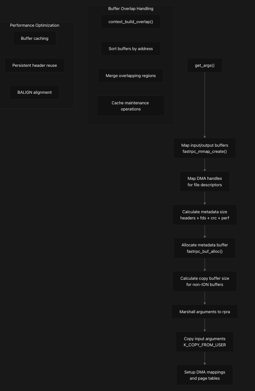
Once the context is established, the system prepares for transmission by calling get_args to set up DMA buffers and map memory regions that will be shared between the host and DSP. The get_args function implements sophisticated argument marshaling that handles both ION buffers and regular memory through a multi-stage pipeline. It first maps input/output buffers by calling fastrpc_mmap_create for each file descriptor, creating DMA mappings and SMMU translations.
The function then calculates metadata size requirements for headers, file descriptors, CRC, and performance counters, followed by allocating metadata buffers through fastrpc_buf_alloc. For non-ION buffers, it copies input arguments from user space using K_COPY_FROM_USER and sets up the remote procedure call argument structure (rpra) with proper DMA mappings and page tables. This step is crucial because it handles the complex memory management required for cross-processor communication, including SMMU mappings and cache coherency considerations. The prepared message is then transmitted to the DSP through fastrpc_transport_send, which abstracts the underlying transport mechanism. Let’s look at the next sections in detail next which would make this process clear.
Memory Management
The FastRPC memory management system implements a sophisticated buffer mapping architecture that coordinates memory access between user space, kernel space, and DSP virtual address spaces. This system handles multiple types of memory mappings and buffer allocations to enable efficient communication with remote DSP processors through a hierarchical allocation approach and comprehensive mapping capabilities .
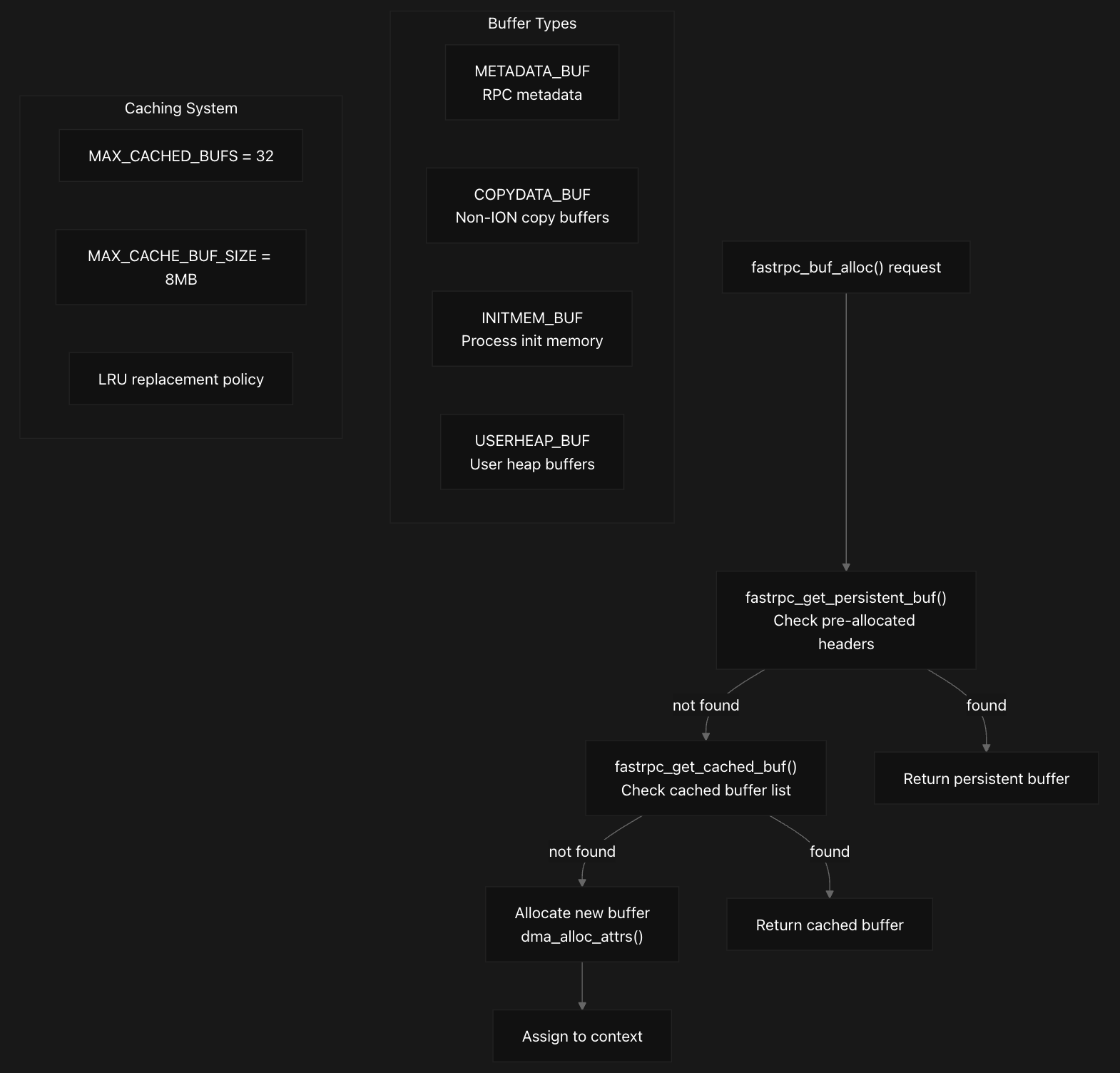
The system uses a three-tier buffer allocation strategy where fastrpc_buf_alloc first checks for persistent buffers through fastrpc_get_persistent_buf, then searches cached buffers via fastrpc_get_cached_buf, and finally allocates new buffers using dma_alloc_attrs if neither option is available. The persistent buffer mechanism is optimized for metadata buffers under one page size, utilizing pre-allocated header buffers that can be reused across multiple RPC calls . The caching system maintains a list of previously allocated buffers in fl->cached_bufs to optimize performance by avoiding repeated allocations, with the system supporting up to 32 cached buffers with a maximum size of 8MB each, selecting the smallest buffer that fits the requested size to minimize memory waste.
Buffer Types and Allocation Strategy
The system defines four distinct buffer types in the fastrpc_buf_type enumeration:
METADATA_BUFfor small control structuresCOPYDATA_BUFfor data copying operationsINITMEM_BUFfor process initialization memoryUSERHEAP_BUFfor user-allocated heap buffers
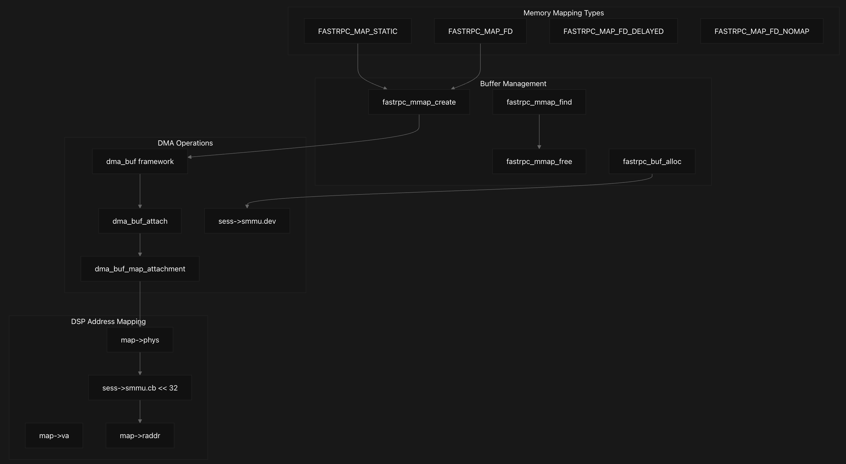
Memory mapping operations are coordinated through fastrpc_mmap_create which handles different mapping types including static maps, file descriptor maps, and delayed maps, supporting different flags like FASTRPC_MAP_FD, FASTRPC_MAP_FD_DELAYED, and FASTRPC_MAP_FD_NOMAP. Each mapping type follows a different code path within this function, with FASTRPC_MAP_FD_NOMAP creating mappings without full DMA setup, while other types perform complete DMA buffer attachment and mapping.
Memory Mapping Structure and Lifecycle
1
2
3
4
5
6
7
8
9
10
11
12
13
14
15
16
17
18
19
20
21
22
23
24
25
26
27
28
29
30
31
32
struct fastrpc_mmap {
	struct hlist_node hn;
	struct fastrpc_file *fl;
	struct fastrpc_apps *apps;
	int fd;
	uint32_t flags;
	struct dma_buf *buf;
	struct sg_table *table;
	struct dma_buf_attachment *attach;
	struct ion_handle *handle;
	uint64_t phys;
	size_t size;
	uintptr_t va;
	size_t len;
	int refs;
	uintptr_t raddr;
	int secure;
	bool is_persistent;			/* the map is persistenet across sessions */
	int frpc_md_index;			/* Minidump unique index */
	uintptr_t attr;
	bool in_use;				/* Indicates if persistent map is in use*/
	struct timespec64 map_start_time;
	struct timespec64 map_end_time;
	/* Mapping for fastrpc shell */
	bool is_filemap;
	bool is_dumped;				/* flag to indicate map is dumped during SSR */
	char *servloc_name;			/* Indicate which daemon mapped this */
	/* Indicates map is being used by a pending RPC call */
	unsigned int ctx_refs;
	/* Map in use for dma handle */
	unsigned int dma_handle_refs;
};
Each memory mapping is represented by a fastrpc_mmap structure that tracks all relevant information including physical address (map->phys), virtual address (map->va), remote DSP address (map->raddr), and DMA buffer details.
The lifecycle is managed through reference counting, with fastrpc_mmap_free handling cleanup by unmapping DMA buffers, detaching from the DMA buffer framework, and performing security context cleanup when necessary. The fastrpc_mmap_find function locates existing mappings by matching file descriptors, virtual addresses, and buffer objects, while fastrpc_mmap_remove handles cleanup by searching both global and per-file mapping lists and ensuring proper reference counting before removal.
DMA Operations and Buffer Management
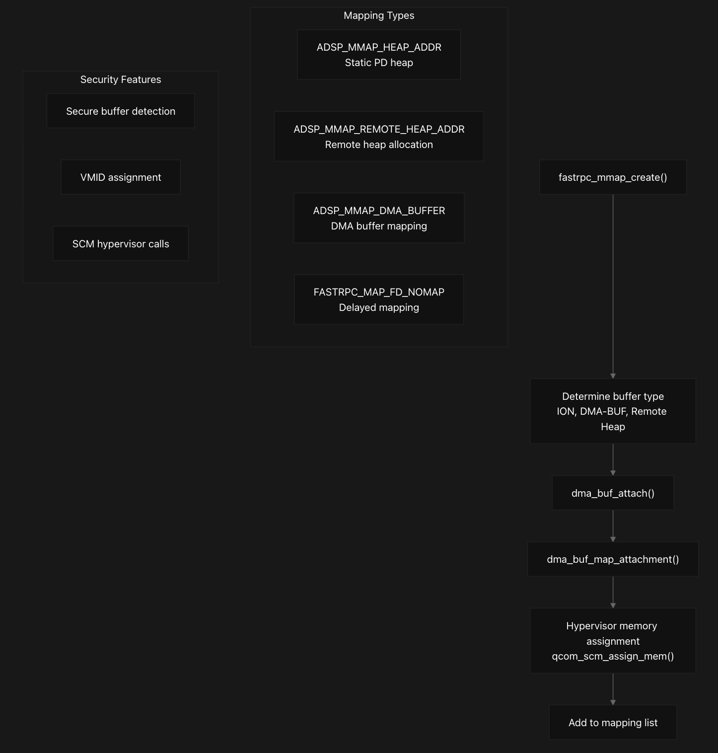
The memory management system integrates deeply with the Linux DMA buffer framework, where for each mapping, the system calls dma_buf_attach to attach the buffer to the appropriate SMMU device, followed by dma_buf_map_attachment to create the actual mapping. The physical address is extracted from the scatter-gather table, and if an SMMU context bank is configured, the address is adjusted by shifting the context bank ID into the upper 32 bits to create the final DSP-accessible address stored in map->raddr.
The system determines buffer security properties through set_buffer_secure_type, which examines VMID permissions to classify buffers as secure or non-secure based on exclusive access patterns, and for secure buffers, performs hypervisor memory assignment using qcom_scm_assign_mem to grant appropriate permissions to both HLOS and DSP domains. Next, we’ll explore Session and SMMU Management, as they are closely tied to memory management and DMA operations.
Session and SMMU Management
The FastRPC DSP kernel system implements Session and SMMU (System Memory Management Unit) management that integrates secure memory mapping, context isolation, and DMA operations between user space and DSP subsystems. This architecture provides both security isolation and performance optimization through context bank sharing and coherent memory access patterns.
Session Management and SMMU Integration
1
2
3
4
5
6
7
8
9
10
11
12
13
14
15
16
17
18
19
20
21
22
23
24
25
26
27
struct fastrpc_session_ctx {
	struct device *dev;
	struct fastrpc_smmu smmu;
	int used;
};

...

struct fastrpc_smmu {
	struct device *dev;
	const char *dev_name;
	int cb;
	int enabled;
	int faults;
	int secure;
	int coherent;
	int sharedcb;
	int pd_type; /* Process type on remote sub system */
	/* gen pool for QRTR */
	struct gen_pool *frpc_genpool;
	/* fastrpc gen pool buffer */
	struct fastrpc_buf *frpc_genpool_buf;
	/* fastrpc gen pool buffer fixed IOVA */
	unsigned long genpool_iova;
	/* fastrpc gen pool buffer size */
	size_t genpool_size;
};
The core session management revolves around the fastrpc_session_ctx structure (a member of the fastrpc_file struct), which encapsulates both device information and SMMU configuration. Each session context contains an embedded fastrpc_smmu structure that holds critical SMMU parameters including the device reference (sess->smmu.dev), context bank identifier (sess->smmu.cb), and various operational flags controlling memory access behavior.
The session allocation process is handled by fastrpc_session_alloc_locked, which searches through available sessions in a channel to find one matching the required security level, shared context bank preference, and process type. This function ensures that sessions are properly isolated based on security requirements and process types defined by sess->smmu.pd_type.
Context Bank Configuration and Security
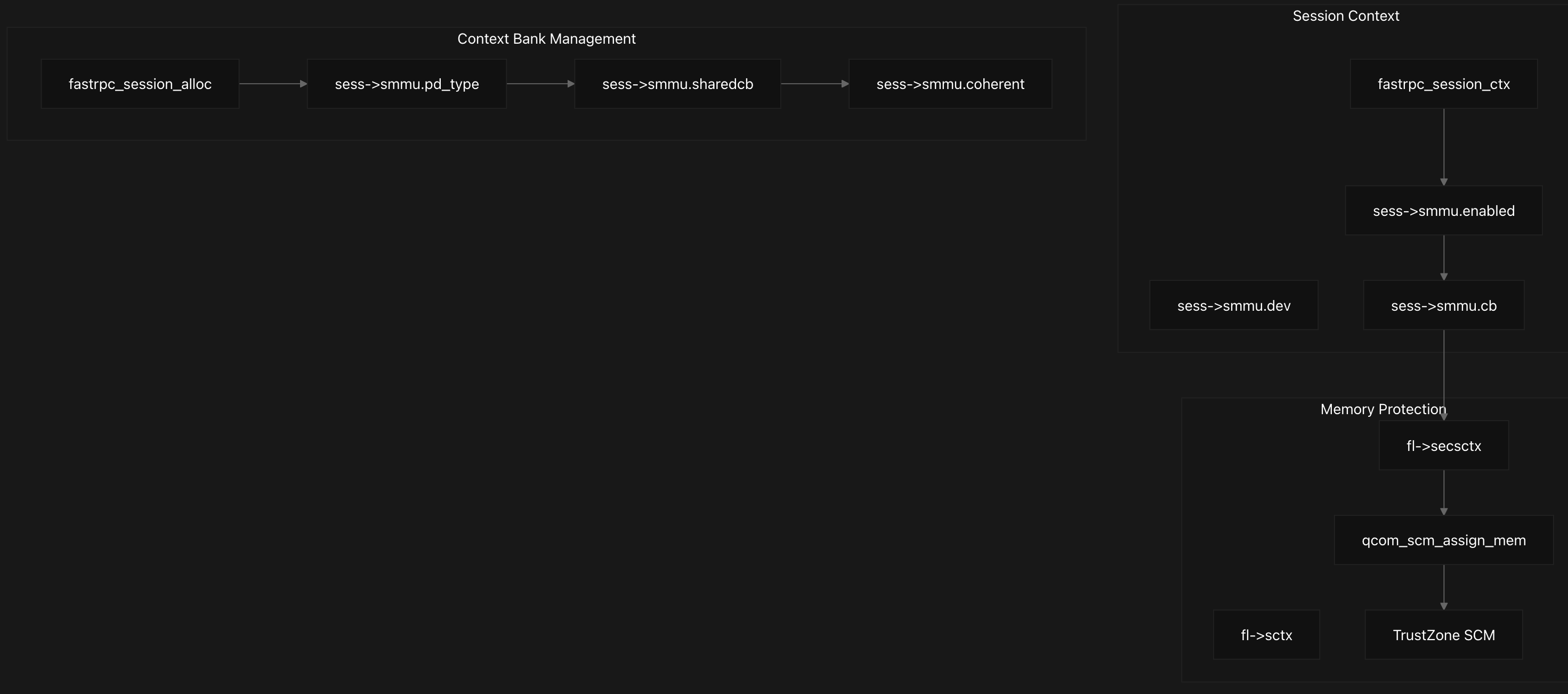
Context banks provide hardware-level memory isolation through the SMMU, supporting both shared and dedicated context banks controlled by the sess->smmu.sharedcb flag. During device tree parsing, properties like dma-coherent set the sess->smmu.coherent flag, while qcom,secure-context-bank determines the security level.
Context bank addressing is implemented through a 32-bit shift operation where the context bank ID is embedded in the upper bits of the physical address (map->phys += ((uint64_t)sess->smmu.cb « 32)). This encoding allows the DSP subsystem to identify which context bank should handle memory accesses for proper isolation, creating domain-specific address spaces for different DSP subsystems while maintaining efficient DMA operations through the shared SMMU infrastructure.
Each FastRPC file context maintains separate session references for secure and non-secure operations through fl->secsctx and fl->sctx respectively. The secure session allocation is handled by fastrpc_session_alloc_secure_memory, which specifically allocates context banks for secure memory operations and integrates with TrustZone through SCM calls.
DMA Operations and Memory Mapping
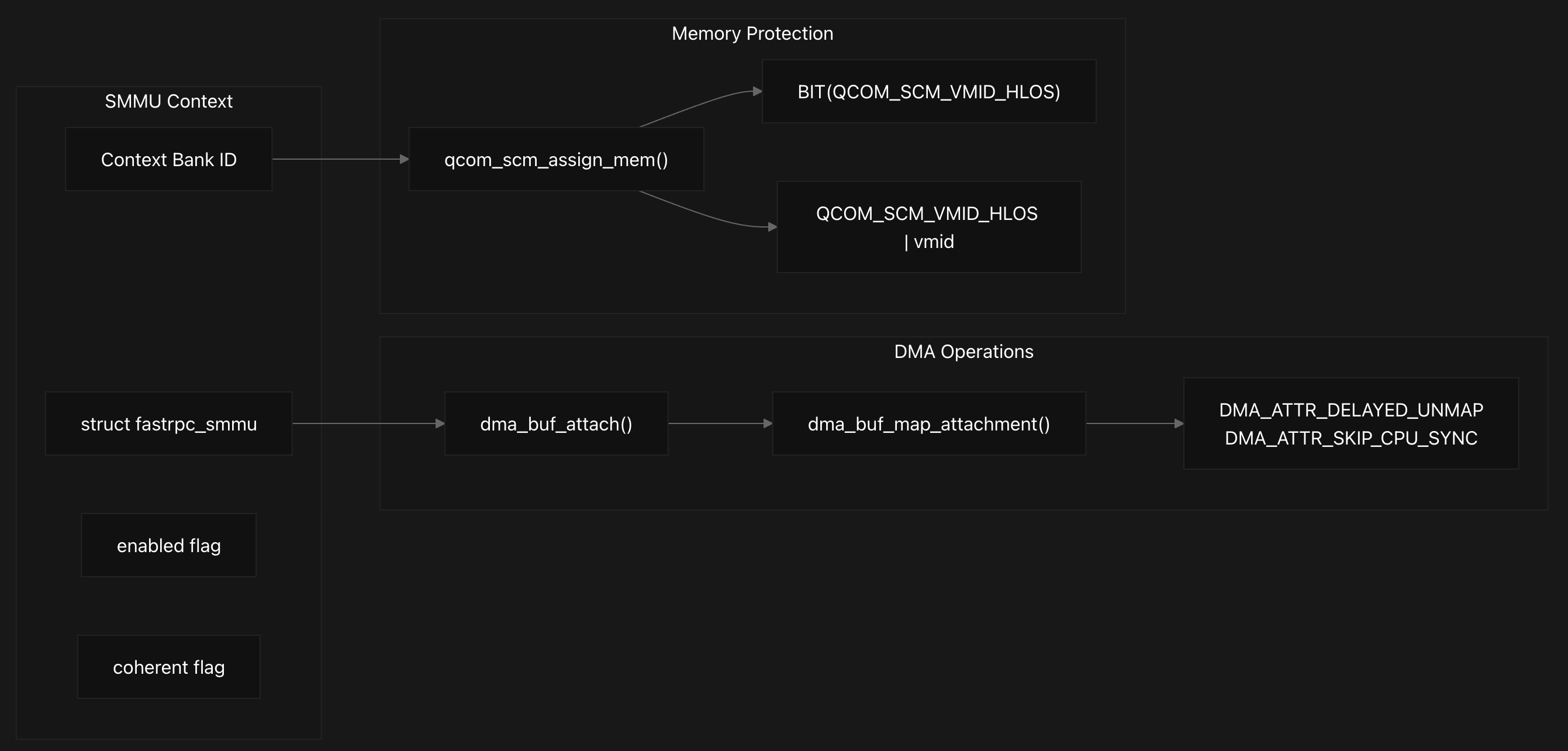
The SMMU integration becomes critical during memory mapping operations, where buffers are attached to the appropriate SMMU device based on security requirements. As discussed earlier, the system performs DMA operations through a sophisticated buffer mapping process that begins with dma_buf_attach to associate buffers with SMMU devices, using the session’s SMMU device context (either secure or non-secure depending on the buffer type).
Following attachment, as we saw earlier, dma_buf_map_attachment creates the actual memory mappings with bidirectional DMA access. The system applies coherency attributes based on sess->smmu.coherent to optimize cache operations.
Memory Protection and Address Encoding
Memory protection is enforced through specific DMA attributes and hypervisor calls. The system applies DMA_ATTR_DELAYED_UNMAP to prevent premature buffer unmapping and DMA_ATTR_SKIP_CPU_SYNC when IO coherency is not supported by the SMMU context.
For secure memory access, the system uses qcom_scm_assign_mem to transfer memory ownership between virtual machines, typically from QCOM_SCM_VMID_HLOS (High Level Operating System) to specific DSP domains.
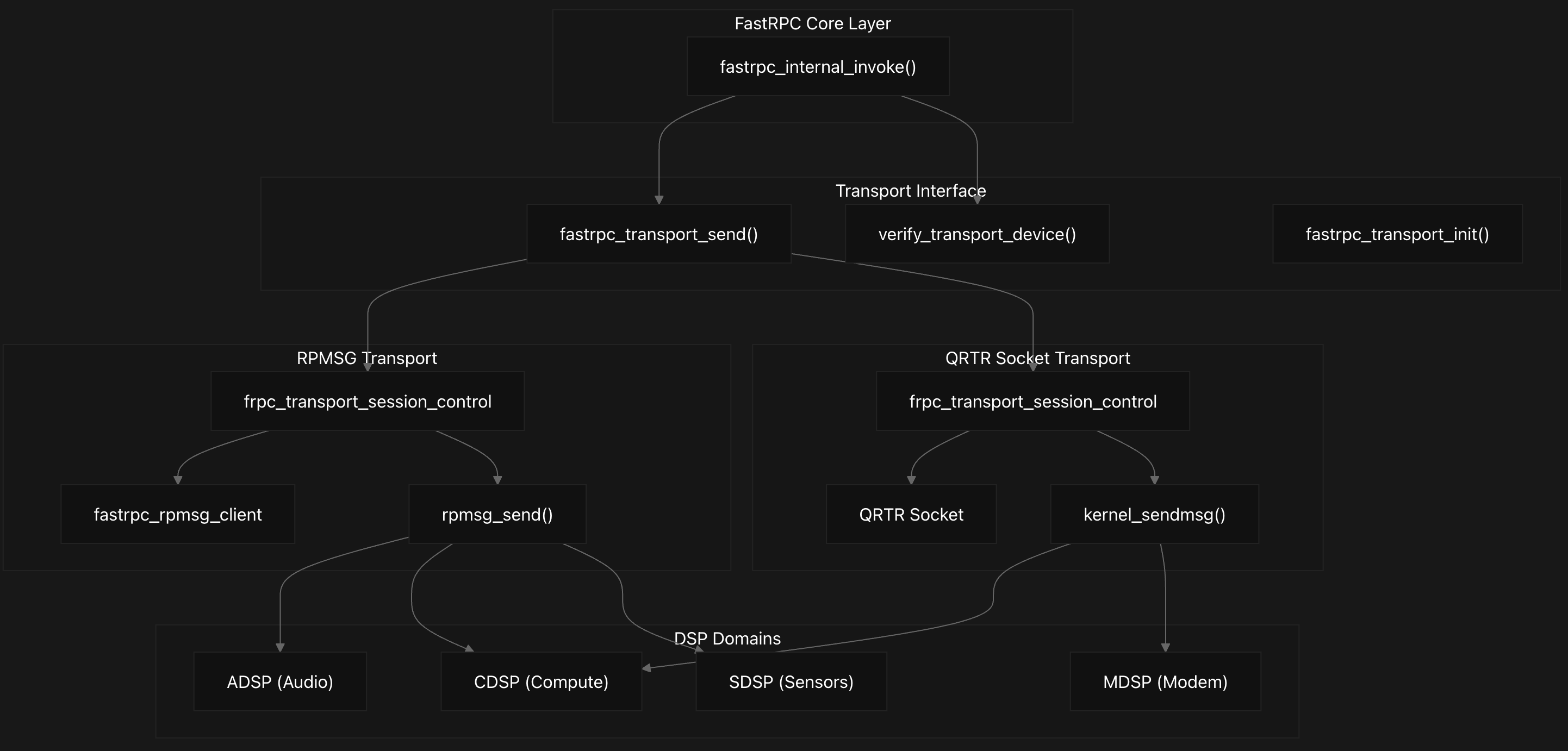
Transport Layer Implementation
The FastRPC transport layer implements a dual-transport architecture that abstracts communication mechanisms between the Linux kernel and different DSP subsystems on Qualcomm platforms, with domain-specific routing handled through a unified interface.
This layer abstracts two distinct transport protocols: RPMSG (Remote Processor Messaging) and QRTR (Qualcomm Router) sockets, enabling RPC message delivery across processor boundaries. The transport selection depends on the target DSP domain, with specific mappings defined for each subsystem.
Each DSP domain uses a specific transport mechanism based on its subsystem requirements:
- The ADSP (Audio DSP) with domain ID 0 uses RPMSG transport through the “lpass” subsystem.
- The MDSP (Modem DSP) with domain ID 1 operates through the “mpss” subsystem.
- The SDSP (Sensor DSP) with domain ID 2 uses the “dsps” subsystem.
- The CDSP (Compute DSP) with domain ID 3 operates through the “cdsp” subsystem.
The fastrpc_transport_send function as discussed earlier serves as the central abstraction layer that routes messages to the appropriate transport mechanism based on the channel ID. This function is called during RPC invocation to send messages to the remote DSP.
RPMSG Transport Implementation
The RPMSG transport uses the Remote Processor Messaging framework for communication. The fastrpc_transport_send function implementation for RPMSG validates the device and sends messages using rpmsg_send. Response handling occurs through fastrpc_rpmsg_callback which processes incoming data and forwards it to fastrpc_handle_rpc_response.
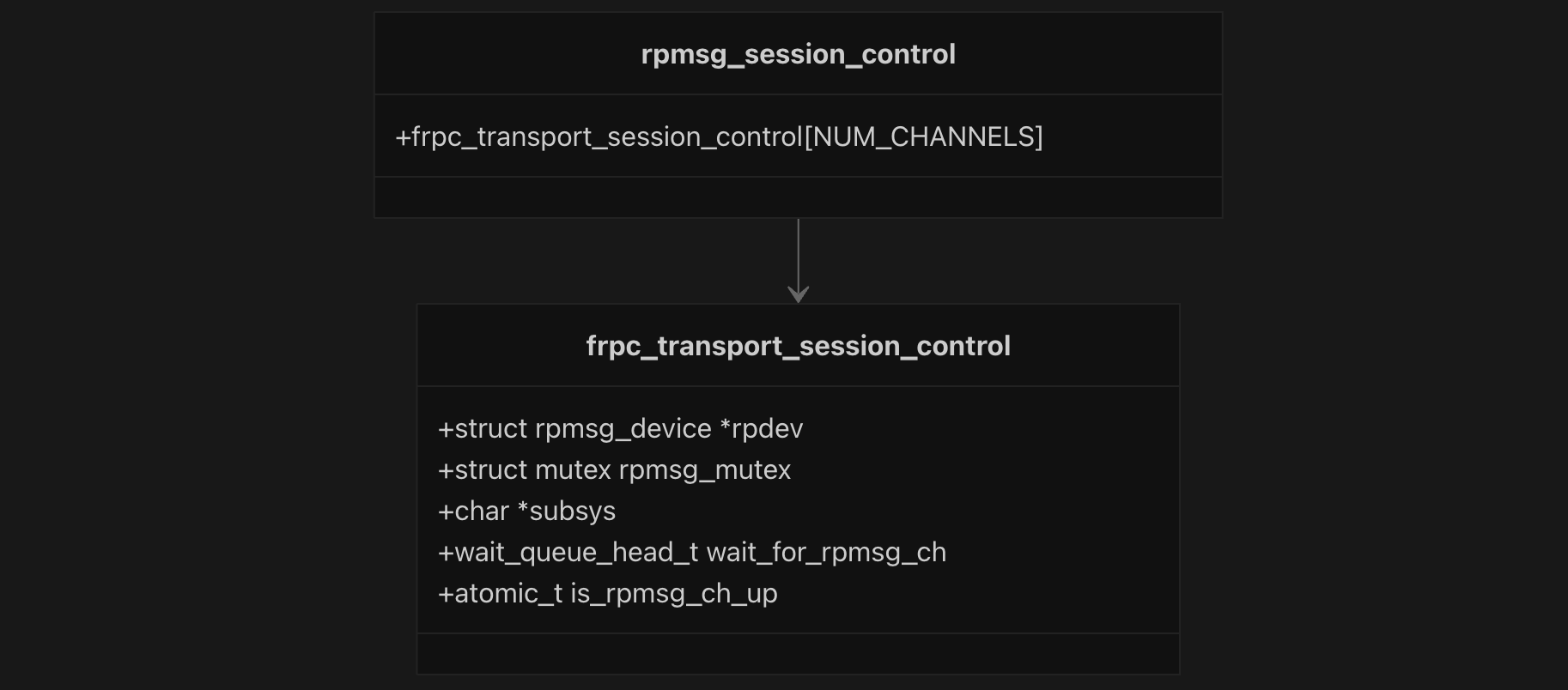
The RPMSG transport maintains session state through the frpc_transport_session_control structure, which contains an rpmsg_device pointer, mutex for synchronization, subsystem name, wait queue for channel availability, and an atomic flag indicating channel status. A global array rpmsg_session_control[NUM_CHANNELS] manages sessions for all channels.
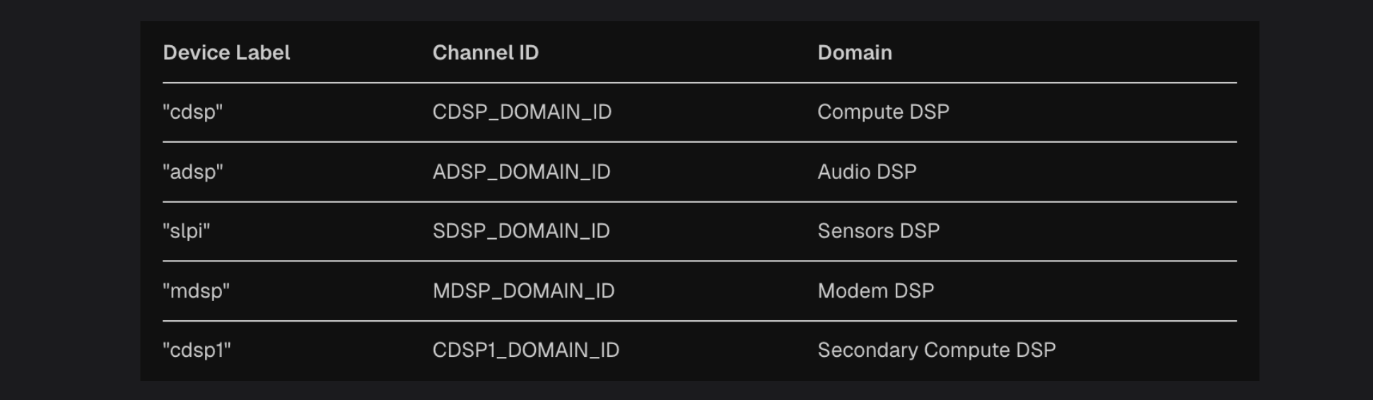
Domain mapping occurs through the get_cid_from_rpdev function, which reads device tree labels to determine the appropriate FastRPC channel ID. The function maps the domain label to the Domain ID.
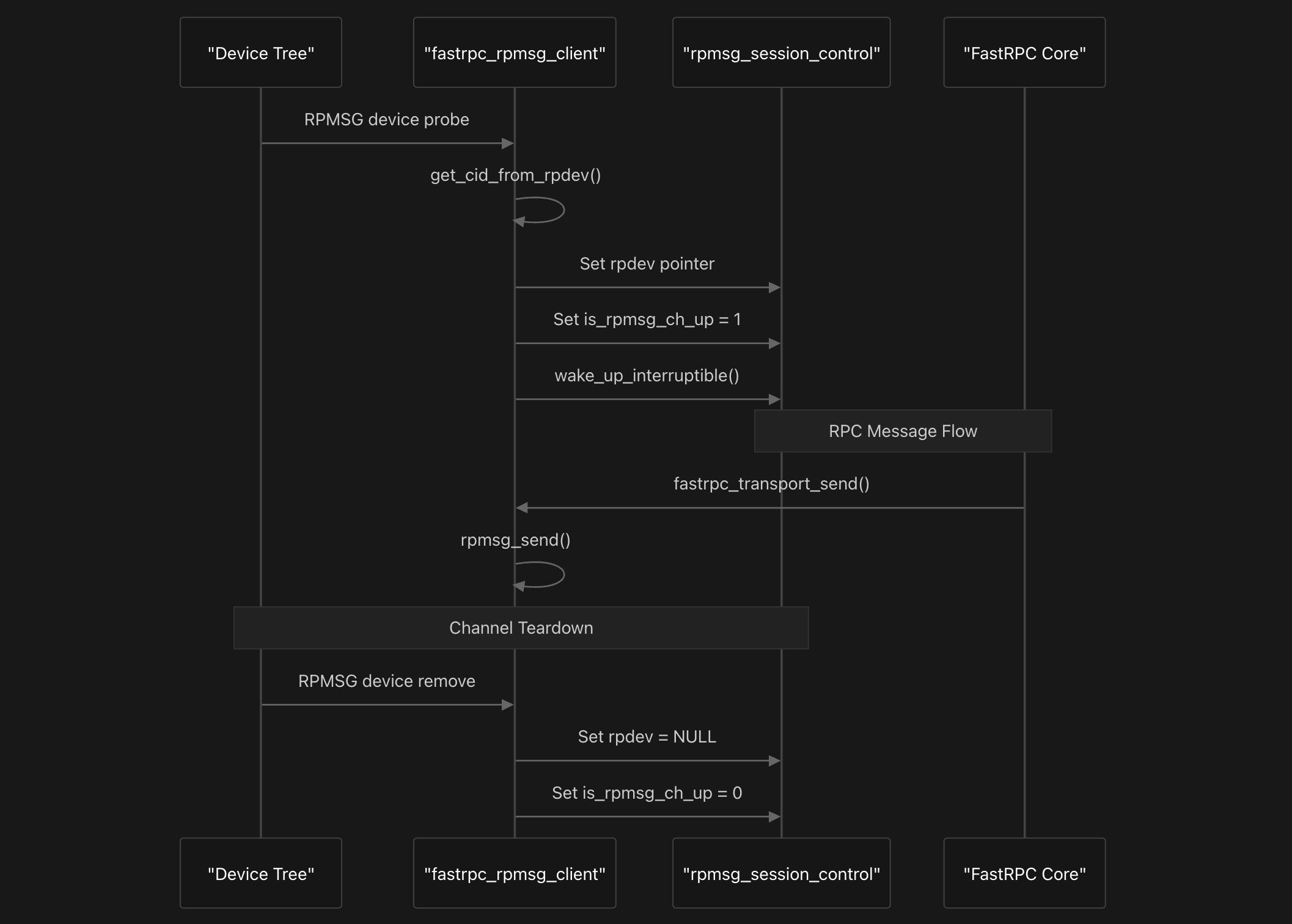
The RPMSG mechanism lifecycle begins when fastrpc_rpmsg_probe is called during device discovery. This function sets the rpdev pointer, marks the channel as up by setting is_rpmsg_ch_up to 1, and wakes up waiting threads. During teardown, fastrpc_rpmsg_remove clears the rpdev pointer and sets the channel status to down.
Message transmission occurs through fastrpc_transport_send, which validates the RPMSG device and calls rpmsg_send to deliver messages to the DSP. This function is called from the core FastRPC layer during RPC invocation. Incoming messages are handled by fastrpc_rpmsg_callback, which validates the channel ID and delegates to fastrpc_handle_rpc_response for processing.
QRTR Socket Transport Implementation
The QRTR socket provides an transport mechanism using the Qualcomm Router protocol. This transport maintains session control through a different structures that includes socket information, remote server instance IDs, and work queues for message handling. Socket-based message transmission is done to transmit RPC messages to remote domains using kernel_sendmsg instead of the RPMSG framework. Response processing occurs through fastrpc_socket_callback which queues work for handling incoming messages.
This implementation provides an alternative communication mechanism to the RPMSG transport, specifically designed for secure domains and specialized remote configurations. The architecture centers around the frpc_transport_session_control structure which encapsulates socket communication state, remote server tracking, and asynchronous message handling through workqueues.
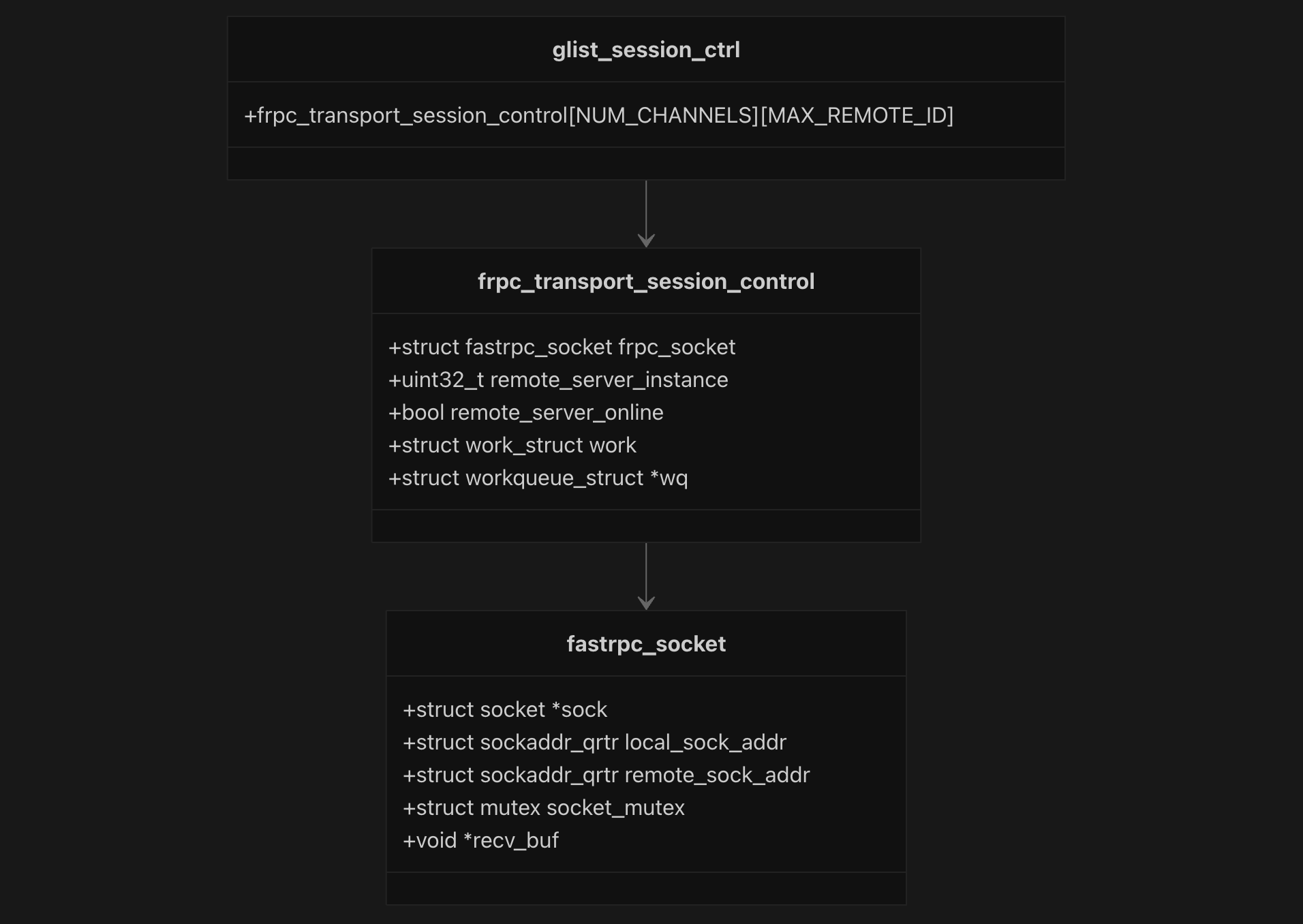
The socket session architecture uses a global session control array glist_session_ctrl[NUM_CHANNELS][MAX_REMOTE_ID] to manage multiple remote domains across different channels. adsprpc_socket.c:86 Each session contains a fastrpc_socket structure that holds the actual socket, local and remote QRTR addresses, synchronization mutex, and receive buffer for incoming messages.
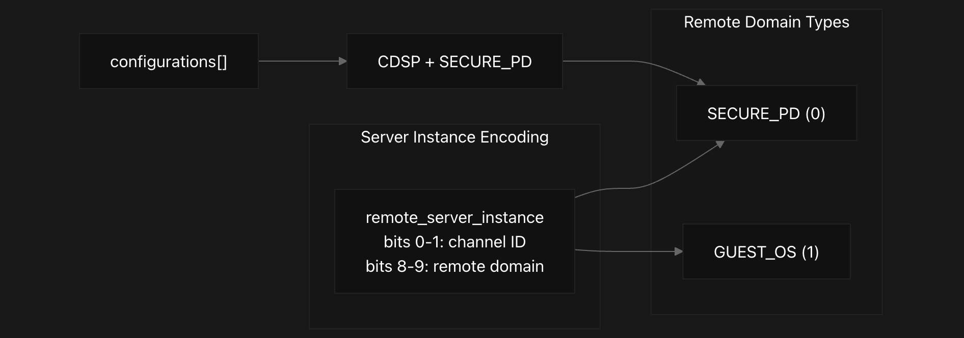
Remote domain configuration is handled through a static configuration table that currently supports CDSP with SECURE_PD domain. The system encodes remote server instances using a bit-mapped scheme where bits 0-1 represent the channel ID and bits 8-9 represent the remote domain type (SECURE_PD=0, GUEST_OS=1).
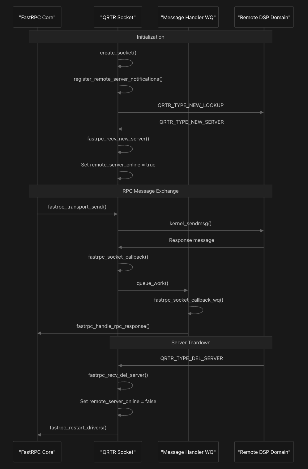
The communication flow begins with socket initialization through create_socket function which creates a kernel QRTR socket and registers callback handlers. The system then registers for remote server notifications using register_remote_server_notifications which sends a QRTR_TYPE_NEW_LOOKUP control packet to discover available remote services.
Control packet handling is managed through fastrpc_recv_ctrl_pkt function which processes QRTR control messages to track remote server availability. When a QRTR_TYPE_NEW_SERVER packet is received, fastrpc_recv_new_server sets the remote server online and stores the remote address, while QRTR_TYPE_DEL_SERVER packets trigger fastrpc_recv_del_server to mark the server offline and initiate driver restart procedures.
Message transmission occurs through a similar function fastrpc_transport_send as we saw earlier, which validates the transport device state and uses kernel_sendmsg to send RPC messages to the remote domain. Incoming responses are handled asynchronously through fastrpc_socket_callback which queues work on a dedicated workqueue, and fastrpc_socket_callback_wq processes the actual message reception and routing.
Transport validation is then performed by verify_transport_device which ensures the socket is created, the remote server is online, and proper mutex protection is in place before allowing message transmission. This validation mechanism ensures reliable communication by preventing attempts to send messages when the transport layer is not properly established or when remote servers are unavailable.
As we see, both transport mechanics discussed above integrate with the core FastRPC system through common interface functions like allowing the upper layers to remain transport-agnostic. The transport initialization registers the appropriate driver based on the build configuration, with RPMSG using register_rpmsg_driver and socket transport creating and configuring sockets for enabled domains. Next, we’ll explore the driver interface, which provides a clearer view of the transport layer implementation we saw just now.
Kernel Driver Interface
The Kernel Driver Interface in the FastRPC system provides a comprehensive programming interface that allows other kernel modules to register as FastRPC drivers and interact with DSP subsystems. This interface follows the Linux device driver model, implementing a bus-type architecture where FastRPC devices and drivers are managed through registration and matching systems.
Interface and Device Management
The interface centers around two primary structures: fastrpc_device and fastrpc_driver.
1
2
3
4
5
6
7
8
struct fastrpc_device {
	struct hlist_node hn;
	struct device dev;
	int handle;
	struct fastrpc_file *fl;
	bool dev_close;
	unsigned int refs;
};
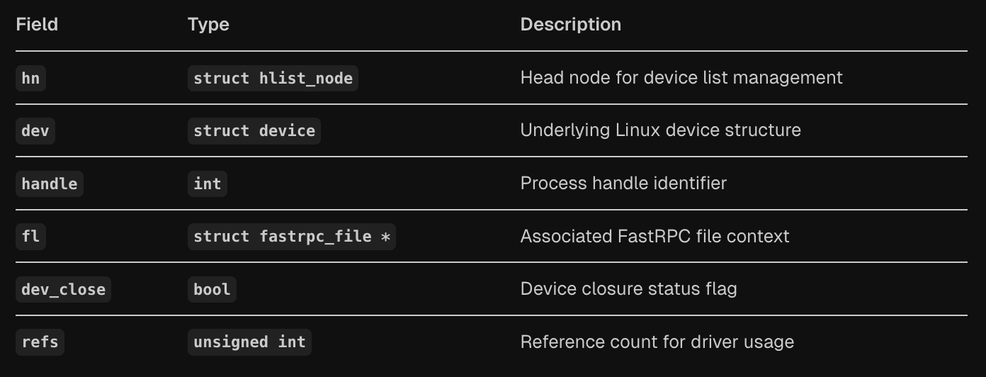
The fastrpc_device structure represents a device instance in the FastRPC bus system, containing fields for device list management (hn), the underlying Linux device structure (dev), process handle identifier (handle), associated FastRPC file context (fl), device closure status (dev_close), and reference counting (refs).
1
2
3
4
5
6
7
8
9
10
struct fastrpc_driver {
	struct hlist_node hn;
	struct device_driver driver;
	struct device *device;
	int handle;
	int create;
	int (*probe)(struct fastrpc_device *dev);
	int (*callback)(struct fastrpc_device *dev,
					enum fastrpc_driver_status status);
};
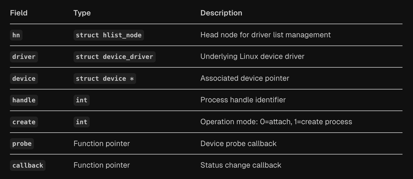
The fastrpc_driver structure defines drivers that can handle FastRPC devices, including the underlying Linux device driver (driver), associated device pointer (device), process handle (handle), operation mode flag (create), and callback functions for device probing (probe) and status changes (callback). The system implements a complete bus infrastructure with matching, probing, and removal operations through the fastrpc_bus_type structure.
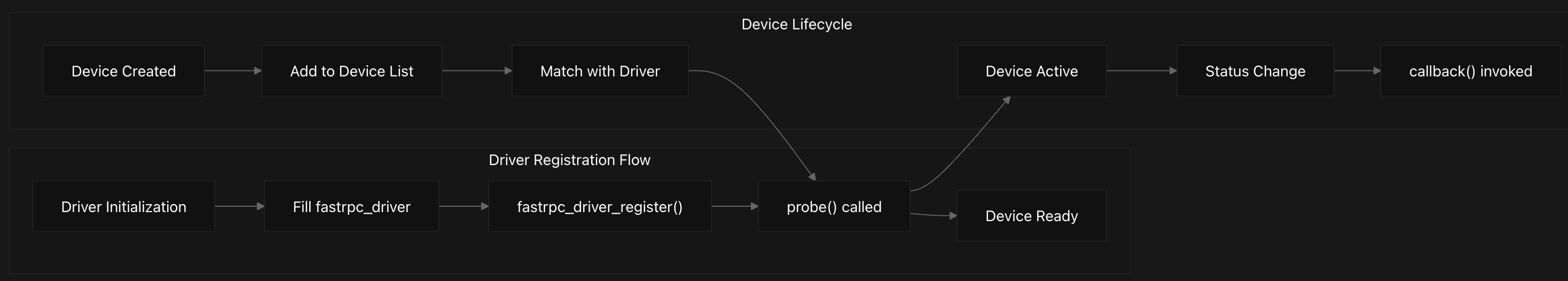
Driver Registration and Lifecycle Management
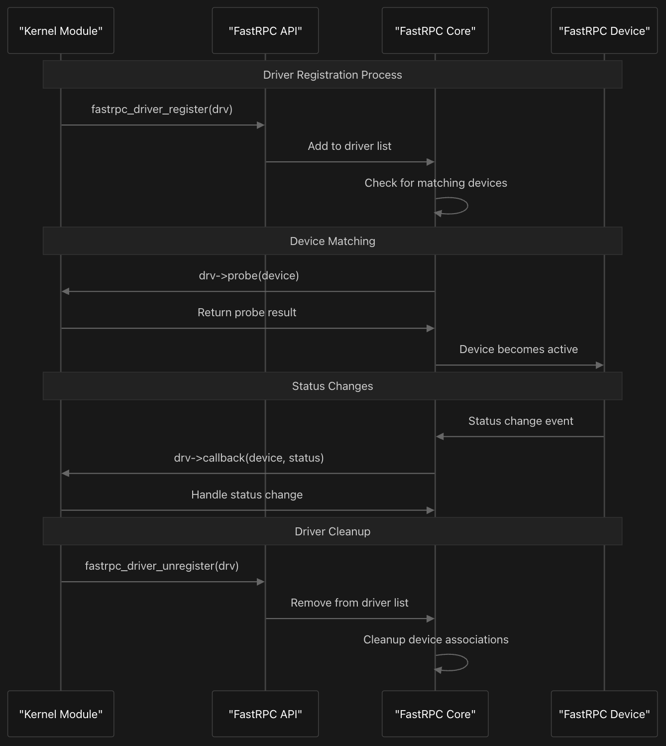
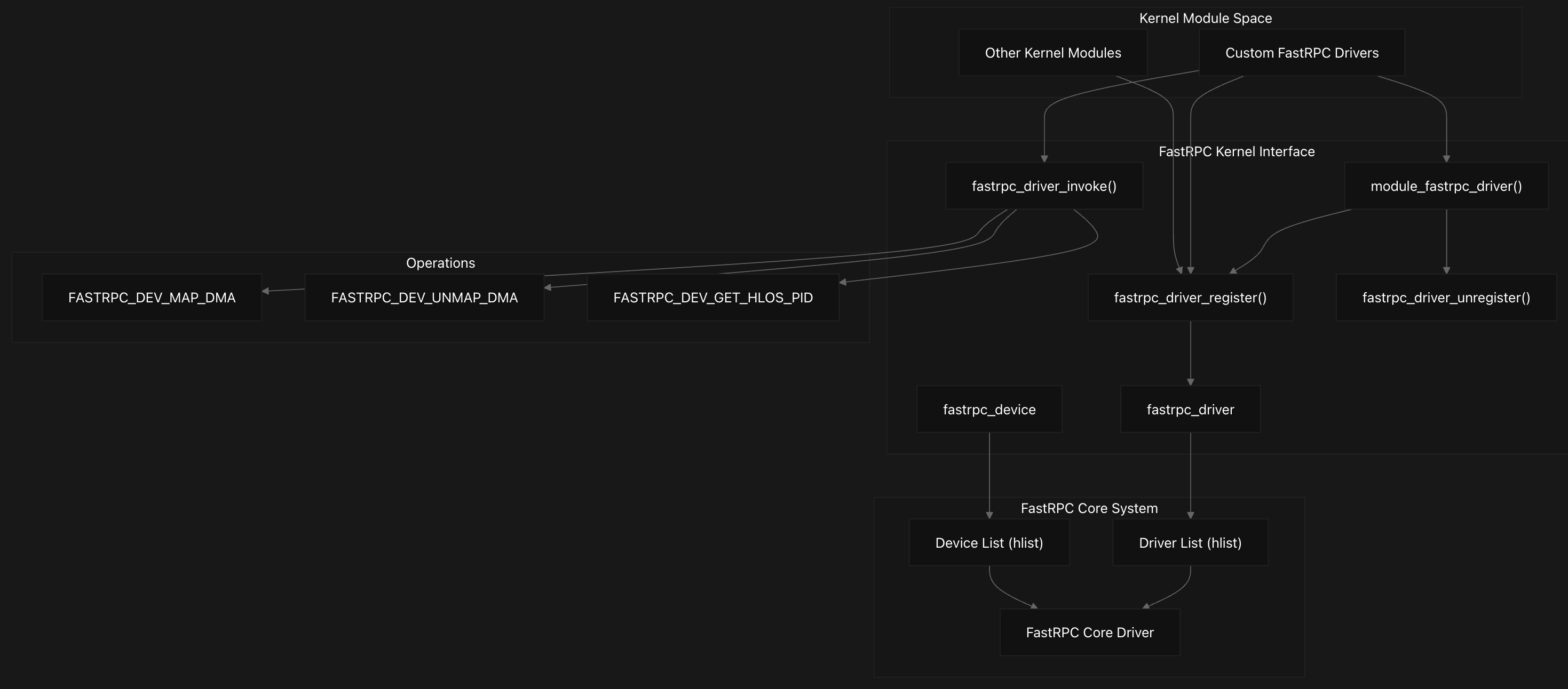
Kernel modules register with the FastRPC system using fastrpc_driver_register and fastrpc_driver_unregister functions. The driver registration process involves adding the driver to the global driver list and checking for matching devices. When a match is found through the fastrpc_bus_match function, the driver’s probe callback is invoked, and the device becomes active.
The system provides a convenient module_fastrpc_driver macro that automatically generates module initialization and cleanup code, eliminating boilerplate for simple drivers. This macro creates __init and __exit functions that handle driver registration and unregistration automatically.
DMA Buffer Management and Driver Operations
1
2
3
4
5
6
7
8
9
10
11
12
13
14
15
16
17
18
19
struct fastrpc_dev_map_dma {
    struct dma_buf *buf;      // Shared DMA buffer object
    uint32_t attrs;           // IOMMU mapping attributes
    size_t size;              // Buffer size in bytes
    uint64_t v_dsp_addr;      // DSP virtual address after mapping
};

...

struct fastrpc_dev_unmap_dma {
    struct dma_buf *buf;      // Shared DMA buffer object
    size_t size;              // Buffer size in bytes
};

...

struct fastrpc_dev_get_hlos_pid {
    int hlos_pid;             // HLOS PID of attached device
};
The interface provides sophisticated DMA buffer management through the fastrpc_driver_invoke function, which supports three primary operations defined in the fastrpc_driver_invoke_nums enumeration. These operations include FASTRPC_DEV_MAP_DMA for mapping DMA buffers to DSP virtual address space, FASTRPC_DEV_UNMAP_DMA for unmapping buffers, and FASTRPC_DEV_GET_HLOS_PID for retrieving host process IDs.
The DMA mapping operations use specialized structures like fastrpc_dev_map_dma and fastrpc_dev_unmap_dma that contain DMA buffer objects, IOMMU mapping attributes, buffer sizes, and DSP virtual addresses. The actual implementation handles complex operations including SMMU device mapping, DSP-side mapping, and proper error handling with reference counting.
The system creates FastRPC devices dynamically through fastrpc_device_create, which allocates device structures, sets up device naming based on process IDs and channel IDs, and registers devices with the Linux device model. The device naming scheme incorporates HLOS PID, unique FastRPC process ID, and channel ID to ensure uniqueness across multiple sessions.
APIs and Interfaces
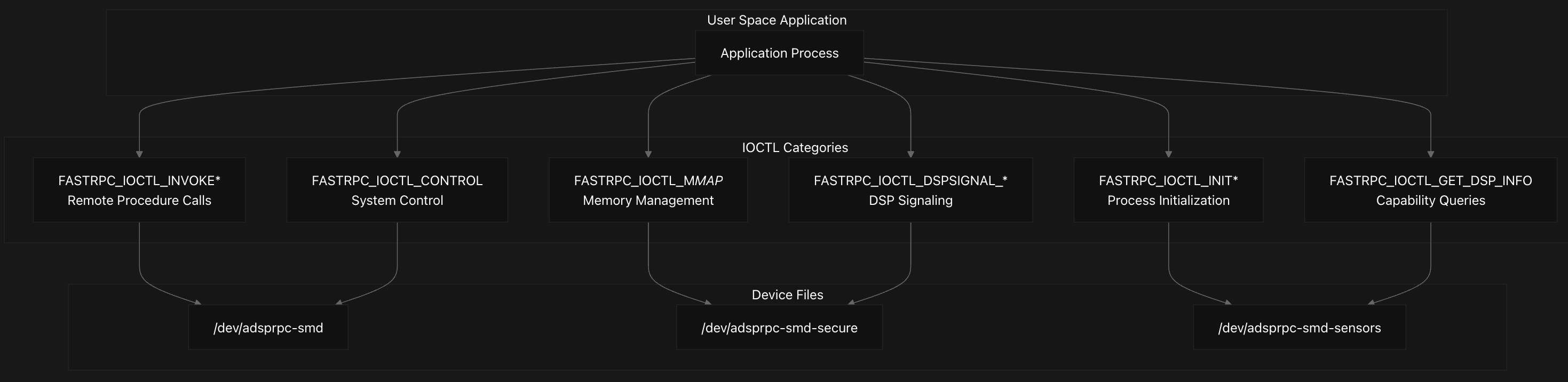
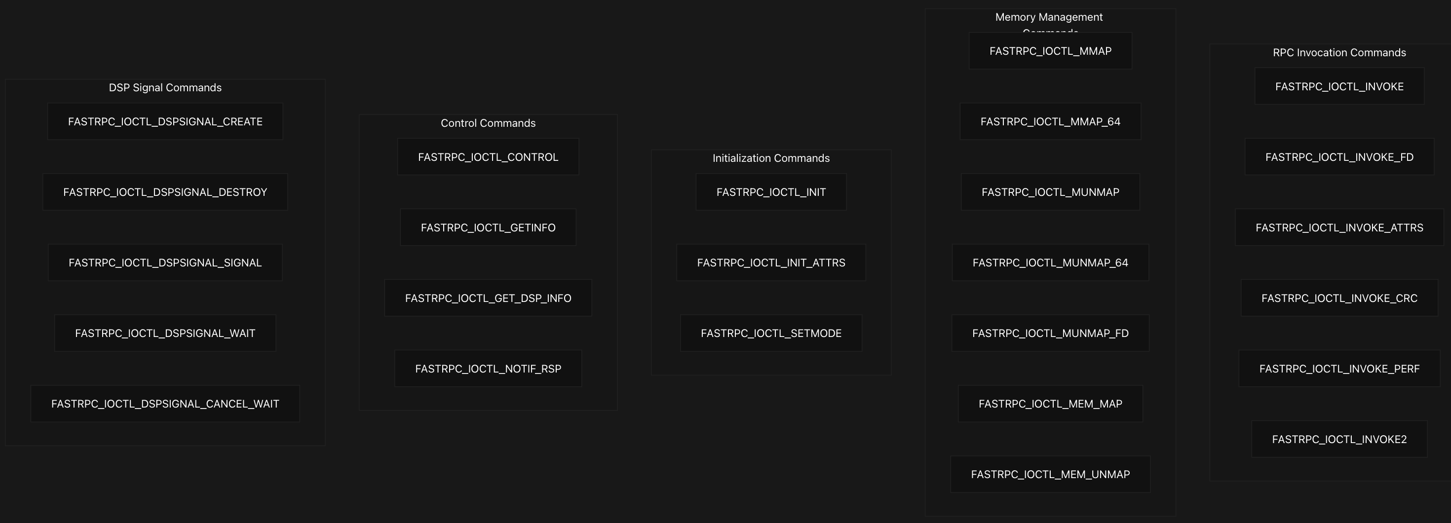
The FastRPC system exposes a comprehensive set of IOCTL commands (22 distinct) through /dev/adsprpc-* device files, enabling user-space applications to invoke remote procedures, manage memory mappings, and control DSP operations. The primary interface for user-space applications consists of IOCTL commands defined with the ‘R’ magic number. These commands are organized into functional categories:
RPC Invocation API
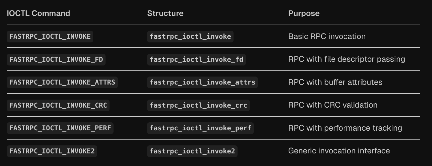
The FastRPC RPC invocation API provides multiple IOCTL commands that enable user-space applications to execute remote procedure calls on DSP subsystems with varying levels of functionality.
The core structure fastrpc_ioctl_invoke contains three essential fields: handle for the remote process handle, sc for scalar parameters describing the argument layout, and pra pointing to the remote arguments array.
1
2
3
4
5
6
7
8
9
10
11
12
13
14
15
16
struct fastrpc_ioctl_invoke {
    uint32_t handle;    /* remote handle */
    uint32_t sc;        /* scalars describing the data */
    remote_arg_t *pra;  /* remote arguments list */
};

struct fastrpc_ioctl_invoke_fd {
	struct fastrpc_ioctl_invoke inv;
	int *fds;		/* fd list */
};

struct fastrpc_ioctl_invoke_attrs {
	struct fastrpc_ioctl_invoke inv;
	int *fds;		/* fd list */
	unsigned int *attrs;	/* attribute list */
};
The API extends this basic structure through several specialized variants that build upon the core invocation. The fastrpc_ioctl_invoke_fd structure adds file descriptor passing capabilities by including an fds array for DMA buffer sharing. The fastrpc_ioctl_invoke_attrs variant further extends this with buffer attributes for cache control and memory management.
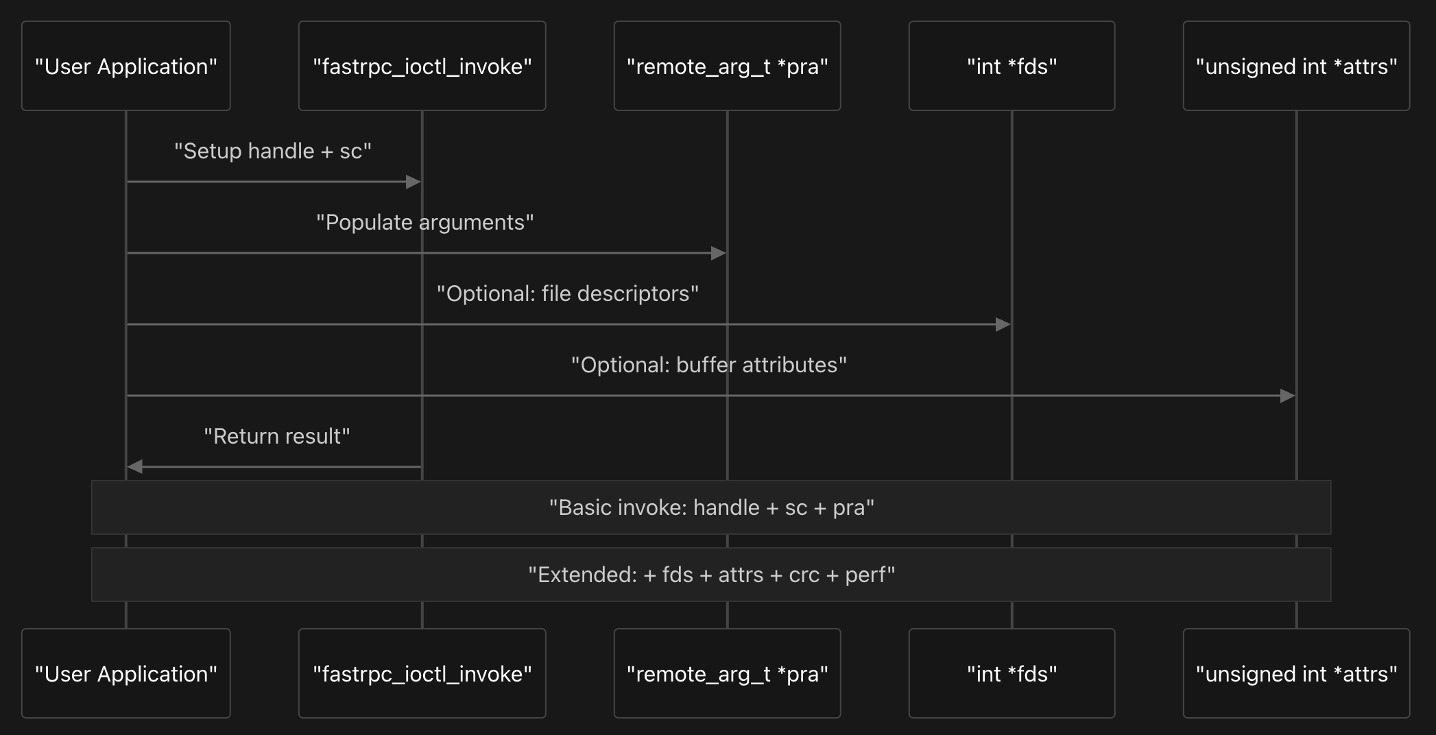
More advanced variants provide additional functionality for data integrity and performance monitoring. The fastrpc_ioctl_invoke_crc structure includes CRC validation capabilities, while the fastrpc_ioctl_invoke_perf variant adds performance tracking through perf_kernel and perf_dsp fields for latency measurement.
The kernel driver processes these invocation requests through the main IOCTL handler, which uses a fallthrough switch statement to handle the different variants efficiently. All invocation types ultimately call fastrpc_internal_invoke via the fastrpc_device_ioctl function as we saw earlier, with the appropriate message type.
Memory Management API
The FastRPC memory management API provides multiple mechanisms for mapping and unmapping memory between user-space and DSP address spaces through various IOCTL commands. The system supports both legacy and modern interfaces, with the modern interface using versioned structures that include reserved fields for future extensions.
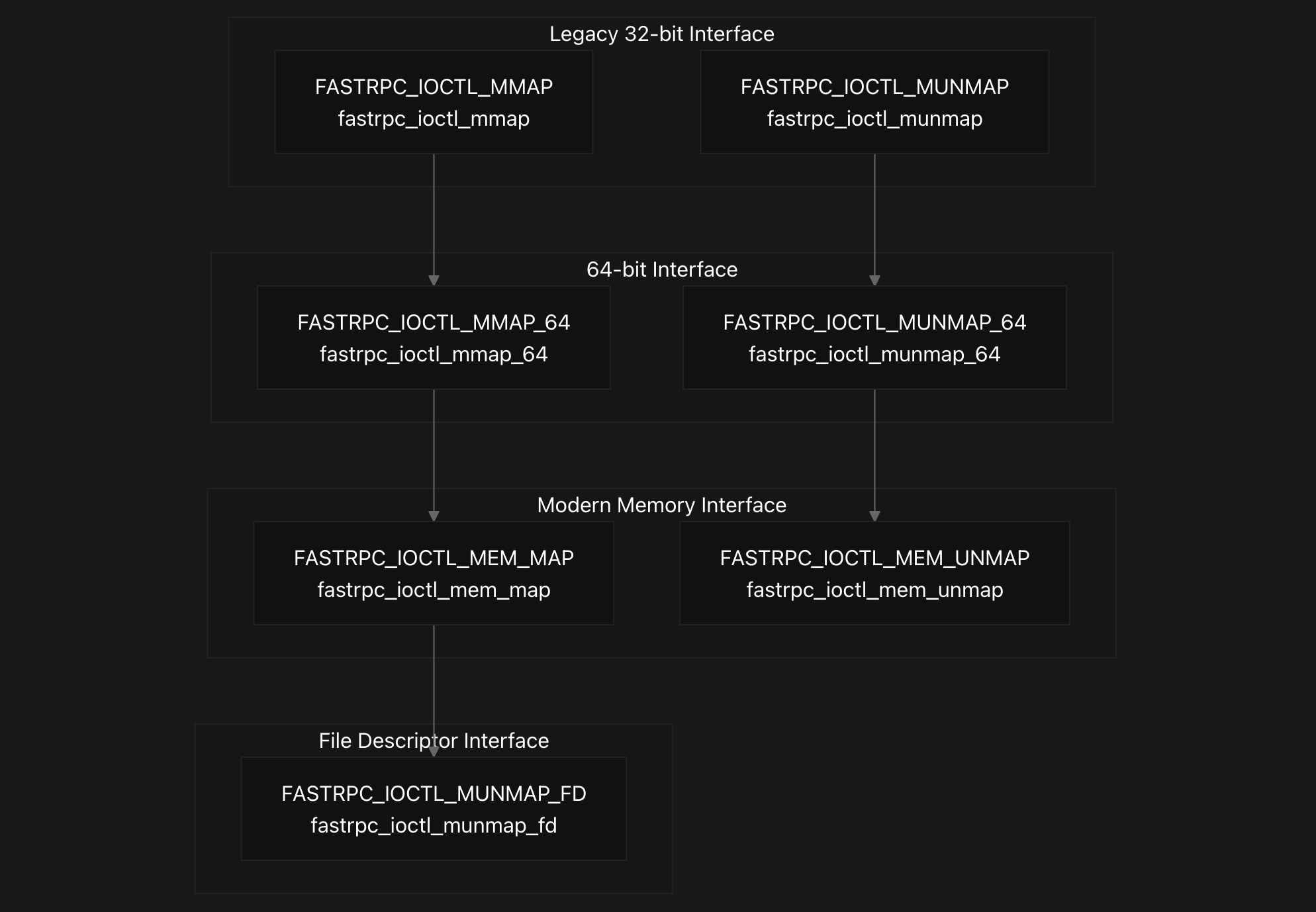
The modern memory mapping interface centers around two primary structures: fastrpc_ioctl_mem_map and fastrpc_ioctl_mem_unmap. The mapping structure contains a version field set to 0 initially and uses a union to either hold the actual mapping parameters in fastrpc_mem_map or reserved space for future extensions. The core mapping parameters include an ION file descriptor, buffer offset, mapping flags, SMMU attributes, input virtual address, buffer length, and an output field for the remote DSP virtual address.
1
2
3
4
5
6
7
8
9
10
11
12
13
14
15
16
17
18
19
20
21
22
23
24
25
26
27
28
29
30
31
32
struct fastrpc_ioctl_mem_map {
    int version;        /* Initial version 0 */
    union {
        struct fastrpc_mem_map m;
        int reserved[MAP_RESERVED_NUM];
    };
};

struct fastrpc_mem_map {
    int fd;             /* ion fd */
    int offset;         /* buffer offset */
    uint32_t flags;     /* flags defined in enum fastrpc_map_flags */
    int attrs;          /* buffer attributes used for SMMU mapping */
    uintptr_t vaddrin;  /* buffer virtual address */
    size_t length;      /* buffer length */
    uint64_t vaddrout;  /* [out] remote virtual address */
};
...

struct fastrpc_ioctl_mem_unmap {
    int version;        /* Initial version 0 */
    union {
        struct fastrpc_mem_unmap um;
        int reserved[UNMAP_RESERVED_NUM];
    };
};

struct fastrpc_mem_unmap {
    int fd;             /* ion fd */
    uint64_t vaddr;     /* remote process (dsp) virtual address */
    size_t length;      /* buffer size */
};
The kernel implementation handles these modern memory operations through fastrpc_internal_mem_map and fastrpc_internal_mem_unmap functions. The mapping process first verifies that DSP process initialization has completed, then creates an SMMU mapping using fastrpc_mmap_create, and finally establishes the DSP-side mapping through fastrpc_mem_map_to_dsp. The unmapping process reverses this by removing the DSP mapping first, then cleaning up the SMMU mapping.
The IOCTL dispatcher in fastrpc_mmap_device_ioctl routes the modern memory commands FASTRPC_IOCTL_MEM_MAP and FASTRPC_IOCTL_MEM_UNMAP to their respective internal handlers. This function also handles the legacy interfaces including FASTRPC_IOCTL_MMAP, FASTRPC_IOCTL_MUNMAP, their 64-bit variants, and the file descriptor-based unmapping command FASTRPC_IOCTL_MUNMAP_FD.
Initialization and Configuration API
The FastRPC initialization API provides a structured way for applications to initialize DSP processes and configure the FastRPC environment through two primary IOCTL commands and their associated data structures.
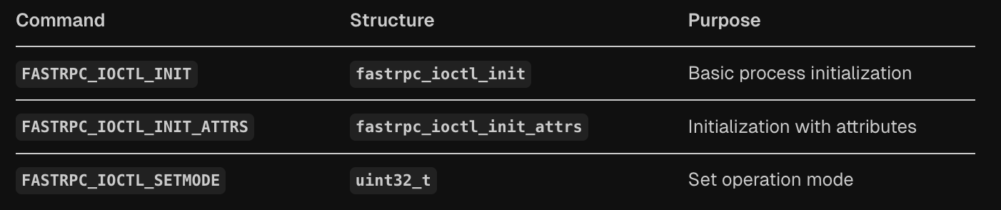
The basic initialization uses FASTRPC_IOCTL_INIT with the fastrpc_ioctl_init structure, while enhanced initialization uses FASTRPC_IOCTL_INIT_ATTRS with the fastrpc_ioctl_init_attrs structure that extends the basic structure with additional attributes and signature length fields.
1
2
3
4
5
6
7
8
9
10
11
12
13
14
15
struct fastrpc_ioctl_init {
    uint32_t flags;     /* one of FASTRPC_INIT_* macros */
    uintptr_t file;     /* pointer to elf file */
    uint32_t filelen;   /* elf file length */
    int32_t filefd;     /* ION fd for the file */
    uintptr_t mem;      /* mem for the PD */
    uint32_t memlen;    /* mem length */
    int32_t memfd;      /* ION fd for the mem */
};

struct fastrpc_ioctl_init_attrs {
    struct fastrpc_ioctl_init init;
    int attrs;
    unsigned int siglen;
};
The core fastrpc_ioctl_init structure contains several key fields that define how the DSP process should be initialized. The flags field specifies the initialization type using FASTRPC_INIT_* macros, which determines whether the process should attach to an existing process, create a new dynamic process, or create a static process. The file and filelen fields point to the ELF binary that will be loaded on the DSP, while filefd provides an ION file descriptor for the binary. Similarly, the mem and memlen fields specify memory allocation for the process domain (PD), with memfd providing the corresponding ION file descriptor for memory management.
The enhanced fastrpc_ioctl_init_attrs structure wraps the basic initialization structure and adds two additional fields: attrs for process attributes and siglen for signature validation length. This extended structure is processed by the same kernel function fastrpc_init_process, which handles both initialization variants by checking the IOCTL command type and setting appropriate default values for the additional fields when using the basic initialization.
Control and Configuration API
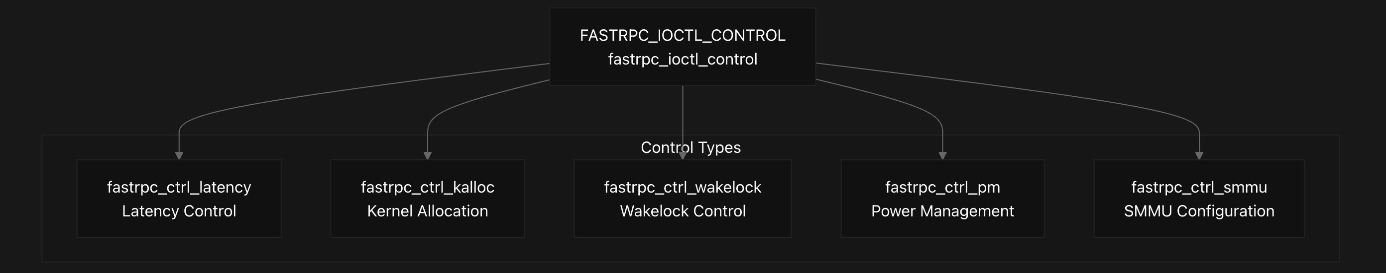
The FastRPC control interface provides runtime configuration capabilities through the FASTRPC_IOCTL_CONTROL command, which uses the fastrpc_ioctl_control structure to manage various system aspects. This structure contains a request type field and a union of different control structures for specific operations.
1
2
3
4
5
6
7
8
9
10
struct fastrpc_ioctl_control {
    uint32_t req;
    union {
        struct fastrpc_ctrl_latency lp;
        struct fastrpc_ctrl_kalloc kalloc;
        struct fastrpc_ctrl_wakelock wp;
        struct fastrpc_ctrl_pm pm;
        struct fastrpc_ctrl_smmu smmu;
    };
};
The control interface supports several key operations through different control types defined in the enumeration. Latency control (FASTRPC_CONTROL_LATENCY) manages power management and performance through the fastrpc_ctrl_latency structure, which allows enabling latency control and setting target latency values in microseconds. The implementation handles PM QoS requests for CPU cores to maintain system responsiveness.
Kernel allocation support is provided through FASTRPC_CONTROL_KALLOC using the fastrpc_ctrl_kalloc stucture. The system automatically reports kernel allocation support as available. Wakelock control (FASTRPC_CONTROL_WAKELOCK) manages system wake state through the fastrpc_ctrl_wakelock structure, though this is restricted to secure device nodes.
Power management is handled via FASTRPC_CONTROL_PM using the fastrpc_ctrl_pm structure to set timeout values for keeping the system awake. The implementation enforces maximum timeout limits and requires prior wakelock enablement. SMMU configuration is managed through FASTRPC_CONTROL_SMMU with the fastrpc_ctrl_smmu structure for shared context bank settings.
1
2
3
4
5
struct fastrpc_ioctl_capability {
    uint32_t domain;
    uint32_t attribute_ID;
    uint32_t capability;
};
The capability query API allows applications to discover DSP capabilities using the fastrpc_ioctl_capability structure. This structure specifies the DSP domain, attribute ID, and receives the capability result. The compatibility layer provides equivalent 32-bit structures for cross-architecture support, with translation functions handling the conversion between 32-bit and 64-bit formats.
DSP Signal API
The DSP Signal API provides inter-process synchronization primitives between user-space and DSP processes through a set of IOCTL operations defined in the FastRPC kernel driver. The system implements a signal-based communication mechanism where user-space processes can create, signal, wait on, and destroy synchronization objects that coordinate with DSP subsystems.
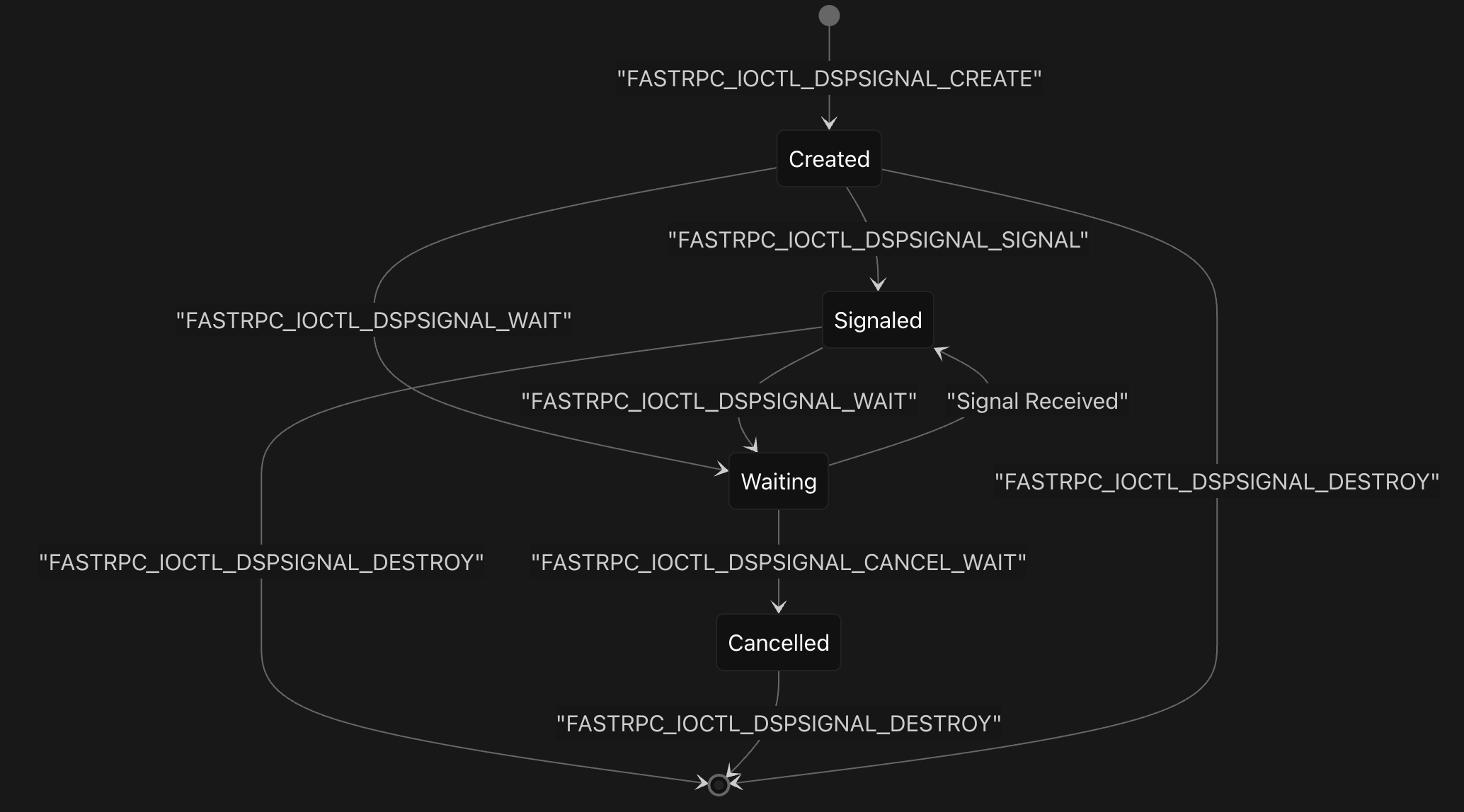
The signal operations are implemented through five main IOCTL commands that handle the complete lifecycle of DSP signals. The FASTRPC_IOCTL_DSPSIGNAL_CREATE operation allocates a new signal with a specified ID and initializes its completion object in the DSPSIGNAL_STATE_PENDING state. The FASTRPC_IOCTL_DSPSIGNAL_SIGNAL operation via the fastrpc_dspsignal_signal function sends a signal message to the DSP using the unique FastRPC process ID, encoding both the process ID and signal ID into a 64-bit message that gets transmitted via the transport layer.
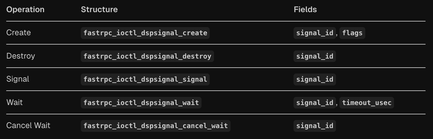
1
2
3
4
5
6
7
8
struct fastrpc_ioctl_dspsignal_wait {
    uint32_t signal_id;     /* Signal ID */
    uint32_t timeout_usec;  /* Timeout in microseconds. UINT32_MAX for infinite wait */
};

struct fastrpc_ioctl_dspsignal_cancel_wait {
	uint32_t signal_id; /* Signal ID */
};
The waiting mechanism is handled by FASTRPC_IOCTL_DSPSIGNAL_WAIT via the fastrpc_ioctl_dspsignal_wait struct, which supports configurable timeouts specified in microseconds, with UINT32_MAX representing an infinite wait. The implementation uses Linux completion objects to block the calling thread until the signal is received from the DSP or the timeout expires. When the DSP responds with a signal, the handle_remote_signal function processes the incoming message, extracts the process ID and signal ID, and completes the corresponding completion object to wake up waiting threads.
The signal structures are organized into groups for efficient memory management, with each fastrpc_file structure containing an array of signal group pointers that are allocated on demand. Each signal maintains state information through the fastrpc_dspsignal structure, which includes a completion object and state field tracking whether the signal is unused, pending, signaled, or canceled. The FASTRPC_IOCTL_DSPSIGNAL_DESTROY operation cleans up signals by setting their state to unused and completing any pending waiters, while FASTRPC_IOCTL_DSPSIGNAL_CANCEL_WAIT via the fastrpc_dspsignal_destroy function allows for early termination of wait operations.
Notification and Async Response API
The FastRPC notification and async response API provides two key mechanisms for handling asynchronous operations and process lifecycle events in the DSP kernel system.
1
2
3
4
5
struct fastrpc_ioctl_notif_rsp {
    int domain;         /* Domain of User PD */
    int session;        /* Session ID of User PD */
    uint32_t status;    /* Status of the process */
};
The notification API delivers status updates about DSP process lifecycle events through the fastrpc_ioctl_notif_rsp structure, which contains the domain ID, session ID, and process status. This notification mechanism is accessed via the FASTRPC_IOCTL_NOTIF_RSP IOCTL command and is processed through fastrpc_get_notif_response in the kernel driver.
1
2
3
4
5
6
7
8
struct fastrpc_ioctl_async_response {
    uint64_t jobid;         /* job id generated by user */
    int result;             /* result from DSP */
    uint64_t *perf_kernel;
    uint64_t *perf_dsp;
    uint32_t handle;
    uint32_t sc;
};
The async response API supports non-blocking RPC operations through the fastrpc_ioctl_async_response structure, which tracks job completion with a user-generated job ID, DSP result code, performance data pointers, and the original handle and scalar parameters. Async operations are initiated through FASTRPC_INVOKE2_ASYNC requests and responses are retrieved via FASTRPC_INVOKE2_ASYNC_RESPONSE through the fastrpc_internal_invoke2 function.
1
2
3
4
5
6
7
8
9
10
11
12
13
14
15
16
17
18
19
union fastrpc_ioctl_param {
    struct fastrpc_ioctl_invoke_async inv;
    struct fastrpc_ioctl_mem_map mem_map;
    struct fastrpc_ioctl_mem_unmap mem_unmap;
    struct fastrpc_ioctl_mmap mmap;
    struct fastrpc_ioctl_mmap_64 mmap64;
    struct fastrpc_ioctl_munmap munmap;
    struct fastrpc_ioctl_munmap_64 munmap64;
    struct fastrpc_ioctl_munmap_fd munmap_fd;
    struct fastrpc_ioctl_init_attrs init;
    struct fastrpc_ioctl_control cp;
    struct fastrpc_ioctl_capability cap;
    struct fastrpc_ioctl_invoke2 inv2;
    struct fastrpc_ioctl_dspsignal_signal sig;
    struct fastrpc_ioctl_dspsignal_wait wait;
    struct fastrpc_ioctl_dspsignal_create cre;
    struct fastrpc_ioctl_dspsignal_destroy des;
    struct fastrpc_ioctl_dspsignal_cancel_wait canc;
};
Both APIs are restricted to the CDSP domain and require specific DSP capabilities to be enabled, as verified during the fastrpc_internal_invoke2 function processing. The complete UAPI parameter union fastrpc_ioctl_param provides type-safe access to all IOCTL parameters including these async and notification structures, ensuring proper memory layout for kernel-userspace communication.
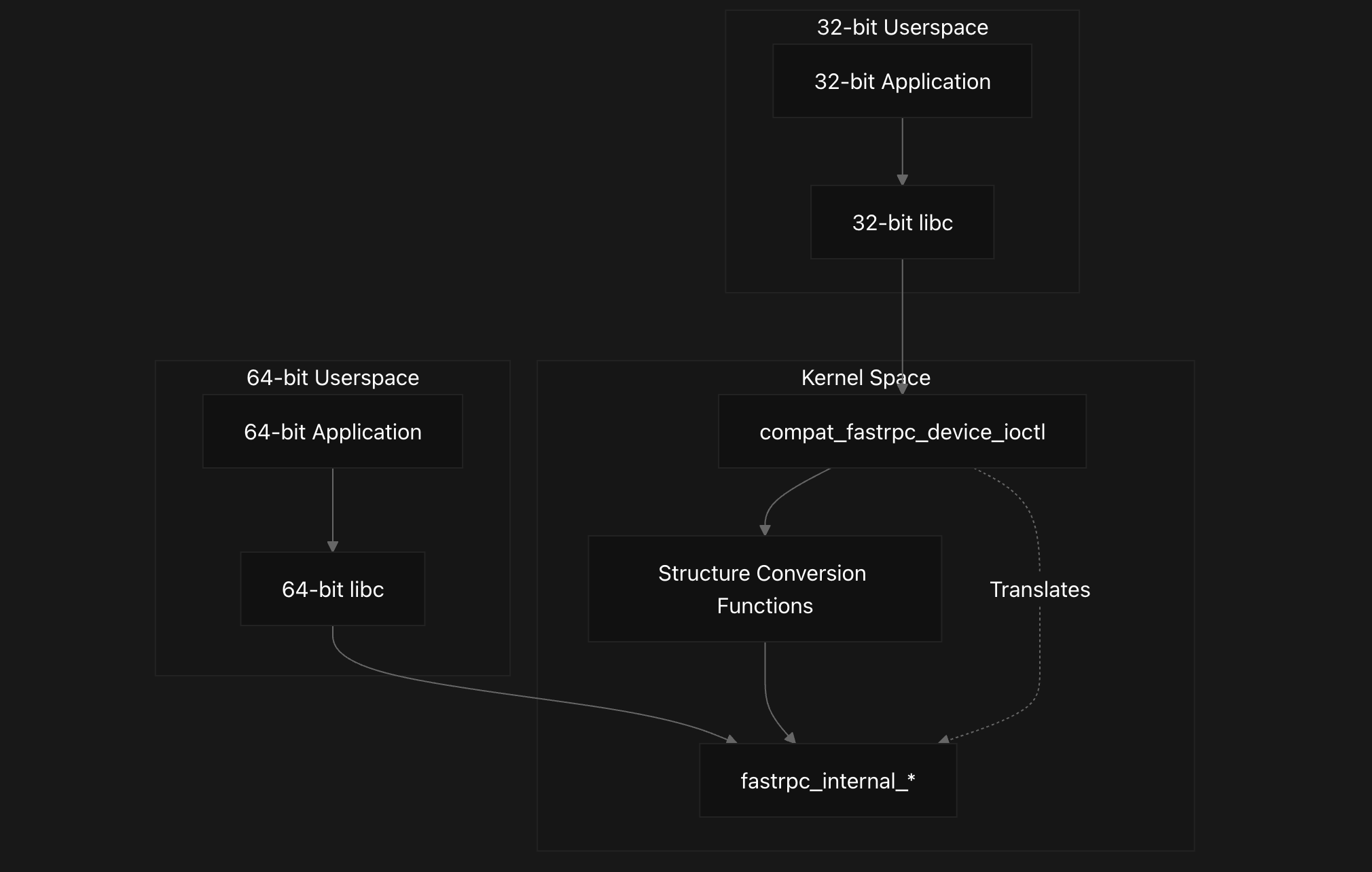
Compatibility Layer
Here we describe the FastRPC 32-bit compatibility layer that enables 32-bit userspace applications to interact with the 64-bit FastRPC kernel driver. The compatibility layer handles data structure translation and IOCTL command mapping between different word sizes.
This compatibility layer addresses the fundamental challenge that pointer sizes, integer sizes, and structure padding differ between 32-bit and 64-bit architectures, which would otherwise prevent 32-bit applications from successfully communicating with the 64-bit kernel driver.
The layer is conditionally compiled based on CONFIG_COMPAT and provides translation services for all FastRPC IOCTL commands including RPC invocation, memory mapping, initialization, and control operations. The related code is present in dsp/adsprpc_compat.c and dsp/adsprpc_compat.h.
The compatibility layer operates as an intermediary translation service between 32-bit userspace applications and the native 64-bit FastRPC driver. It intercepts IOCTL calls from 32-bit processes and performs necessary data structure conversions before forwarding them to the main driver implementation.
The compatibility layer defines parallel IOCTL command constants that correspond to the native FastRPC commands but use compat_ prefixed data structures. These commands use the same IOCTL numbers but different structure definitions. This specialized compat_ data types ensure proper size and alignment handling.
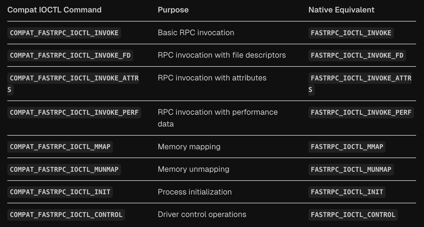
The data types and the conversion flow is shown below -
compat_uptr_t- 32-bit pointer representationcompat_uint_t- 32-bit unsigned integercompat_size_t- 32-bit size typecompat_u64- 64-bit value in 32-bit context
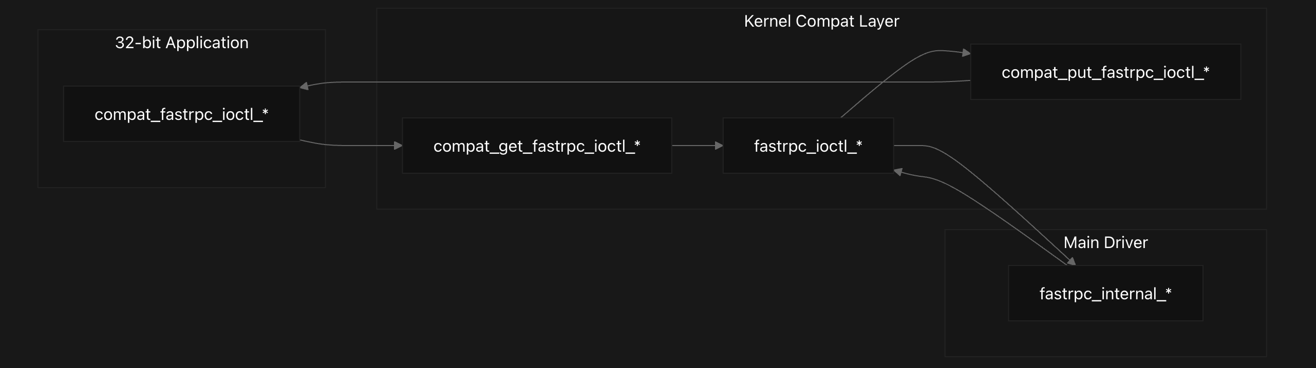
The FastRPC compatibility layer provides seamless 32-bit to 64-bit structure translation for userspace applications. The main dispatcher compat_fastrpc_device_ioctl routes IOCTL commands to specialized conversion handlers that translate data structures between architectures.
The compat_fastrpc_device_ioctl function serves as the central entry point, examining incoming IOCTL commands and routing them to appropriate handlers:
1
2
3
4
5
switch (cmd) {
case COMPAT_FASTRPC_IOCTL_INVOKE:
case COMPAT_FASTRPC_IOCTL_INVOKE_FD:
case COMPAT_FASTRPC_IOCTL_INVOKE_ATTRS:
    return compat_fastrpc_ioctl_invoke(filp, cmd, arg);
The compat_get_fastrpc_ioctl_invoke function handles complex RPC invocation structure translation, including remote argument arrays and file descriptor lists. The function carefully converts pointer arrays by iterating through each remote_arg and translating both buffer pointers and length fields:
1
2
3
4
5
6
7
8
9
10
11
12
13
14
15
16
17
18
19
20
21
22
23
24
25
26
27
28
29
30
31
32
static int compat_get_fastrpc_ioctl_invoke(
			struct compat_fastrpc_ioctl_invoke_async __user *inv32,
			struct fastrpc_ioctl_invoke_async *inv,
			unsigned int cmd, unsigned int sc)
{
	compat_uint_t u = 0;
	compat_size_t s;
	compat_uptr_t p, k;
	union compat_remote_arg *pra32;
	union remote_arg *pra;
	int err = 0, len = 0, j = 0;

	len = REMOTE_SCALARS_LENGTH(sc);

    pra = (union remote_arg *)(inv + 1);
	memcpy(&inv->inv.pra, &pra, sizeof(pra));
	memcpy(&inv->inv.sc, &sc, sizeof(sc));
	err |= get_user(u, &inv32->inv.handle);
	memcpy(&inv->inv.handle, &u, sizeof(u));
	err |= get_user(p, &inv32->inv.pra);
	if (err)
		return err;
	pra32 = compat_ptr(p);
	for (j = 0; j < len; j++) {
		err |= get_user(p, &pra32[j].buf.pv);
		memcpy((uintptr_t *)&pra[j].buf.pv, &p, sizeof(p));
		err |= get_user(s, &pra32[j].buf.len);
		memcpy(&pra[j].buf.len, &s, sizeof(s));
	}
    ...

}
The compat_get_fastrpc_ioctl_mmap function converts memory mapping structures, translating 32-bit virtual addresses to 64-bit kernel addresses. The corresponding compat_put_fastrpc_ioctl_mmap function handles the reverse conversion, ensuring DSP virtual addresses are properly communicated back to 32-bit applications.
The memory mapping dispatcher compat_fastrpc_mmap_device_ioctl handles multiple mapping operations including COMPAT_FASTRPC_IOCTL_MMAP, COMPAT_FASTRPC_IOCTL_MEM_MAP, and COMPAT_FASTRPC_IOCTL_MUNMAP. The compat_get_fastrpc_ioctl_init function converts process initialization structures, handling file pointers and memory descriptors. It translates initialization parameters including file descriptors, memory pointers, and attribute flags while preserving their semantic meaning across architectures.
Conclusion
This concludes our brief walkthrough of the Qualcomm DSP kernel FastRPC implementation internals. We covered the overall architecture, context management, memory management, session and SMMU management, transport layer implementation, kernel driver, associated APIs, and the compatibility layer.
Hopefully, this overview provides helpful context as you dive deeper into the codebase and investigate any related bugs. Thanks for reading!
Credits
Hey There! If you’ve come across any bugs or have ideas for improvements, feel free to reach out to me on X! If your suggestion proves helpful and gets implemented, I’ll gladly credit you in this dedicated Credits section. Thanks for reading!